What is Binary?
Binary is a base-2 number system invented by Gottfried Leibniz, one of four number systems. In this system, it is usually represented by two different symbols 0 and 1 .

In digital electronic circuits, the implementation of logic gates directly uses binary, which is used in modern computers and devices that rely on computers. Each number is called a bit (abbreviation for Binary digit).
In Boolean logic, a single binary digit can only represent True (1) or False (0), however, multiple binary digits can be used to represent large numbers and perform complex functions, any integer can be represented in binary.
In digital data memory, storage, processing, and communications, the 0 and 1 values are sometimes referred to as “low level” and “high level”, respectively.

Binary can also be used to describe compiled software programs, once a program is compiled it contains binary data called “machine code” which can be executed by the computer’s CPU.
What is Octal?
Octal, abbreviated as OCT or O, is a counting system with a base of 8. It employs the eight digits 0, 1, 2, 3, 4, 5, 6, 7, where after 7 it rolls over to 0 and increments the higher digit by 1. In some programming languages, a leading digit of 0 often indicates that the number is in octal. Octal numbers and binary numbers correspond on a bit-by-bit basis (one octal digit corresponds to three binary digits), making octal useful in computer languages.
Octal has been widely used in computer systems like PDP-8, ICL 1900, and large IBM mainframes, which use 12-bit, 24-bit, or 36-bit word lengths. These systems are based on octal since their ideal binary word lengths are multiples of 3 (each octal digit represents three binary digits). Displaying four to twelve digits succinctly represents the entire machine. It also reduces costs as digits can be shown through digital displays, seven-segment displays, and calculators for operator control panels. Binary displays are too complex, and decimal displays require intricate hardware, while hexadecimal displays demand showing more digits.
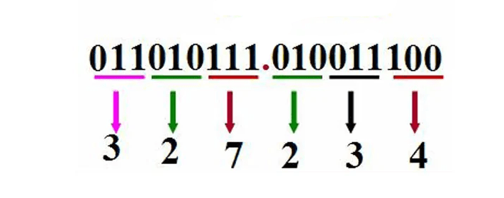
Since one hexadecimal digit corresponds to four binary digits, hexadecimal is more convenient for representing binary. Hence, octal’s application is less widespread than hexadecimal’s. Some programming languages provide the capability to represent numbers using octal notation, and a few older Unix applications still use octal. Computer systems require numeral system conversions internally, using binary as the base. Numeral system conversions between binary, octal, and decimal are accomplished in programming, and FORTRAN77, focused on binary and decimal, handles these conversions.
However, all modern computing platforms use 16, 32, or 64-bit systems, where 64-bit platforms further divide into 8-bit bytes. In these systems, three octal digits satisfy each byte requirement, with the most significant octal digit representing two binary digits (with +1 for the next byte if applicable). Representing 16-bit words in octal requires 6 digits, but the most significant octal digit represents only 1 binary digit (0 or 1). This limitation prevents easy-to-read bytes since they result in 4-bit octal digits.
As a result, hexadecimal is now more commonly used in programming languages, as two hexadecimal digits fully specify a byte. Platforms with powers of two and word sizes make instructions more understandable. The ubiquitous x86 architecture is one such example, though octal is rarely used in this architecture. However, octal can be useful to describe certain binary encodings, such as the ModRM byte, which is split into 2, 3, and 3 bits.
What is Decimal?
Decimal system, often referred to as the base-10 system, is a method of counting where every ten units lead to a higher unit. The first digit holds a positional value of 10^0, the second digit 10^1, the Nth digit 10^(N-1). The value of a number in this system is the sum of each digit’s (value × positional weight).
The decimal counting method is the most widely used in everyday life. It features an increment of ten between adjacent units, forming the basis of decimal notation. This likely stems from the fact that humans typically possess ten fingers, influencing the development of arithmetic using the decimal system. Aristotle observed that humans generally use the decimal system due to the anatomical reality of having ten fingers.
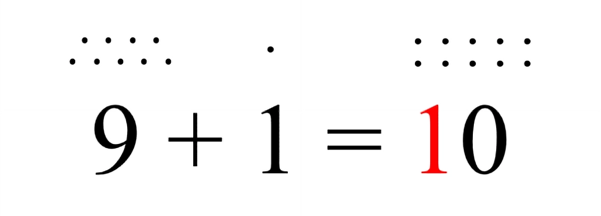
Historically, most of the independently developed written numeral systems employed a decimal base, except for the Babylonian sexagesimal (base-60) and Maya vigesimal (base-20) numeral systems. However, these decimal systems weren’t necessarily positional.
The term “decimal” originates from the Latin word “decem,” meaning ten. The decimal counting method was invented by Hindu mathematicians around 1,500 years ago and was later transmitted by Arabs to the 11th century. It is based on two principles: positional notation and base-ten representation. All numbers are composed of the ten basic symbols, and when a unit reaches ten, it carries over to the next position, making the position of a symbol crucial. The fundamental symbols are the digits 0 through 9.
To represent multiples of ten, the digits are shifted one position to the left with a trailing zero, resulting in 10, 20, 30, and so forth. Similarly, multiples of one hundred involve shifting the digits again: 100, 200, 300, and so on. To express a fraction of ten, the digits are shifted to the right, and zeros are added as needed: 1/10 becomes 0.1, 1/100 becomes 0.01, and 1/1000 becomes 0.001.
What is Hexadecimal?
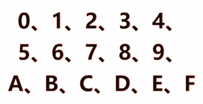
Hexadecimal (abbreviated as hex or subscript 16) is a counting system with a base of 16, which is a base system in which every 16 is added to 1. Usually represented by numbers 0, 1, 2, 3, 4, 5, 6, 7, 8, 9 and letters A, B, C, D, E, F (a, b, c, d, e, f), Among them: A~F represent 10~15, these are called hexadecimal numbers.
For example, the number 57 in decimal is written as 111001 in binary and 39 in hexadecimal. Today’s hexadecimal system is widely used in the computer field, because it is not difficult to convert 4 bits (Bit) into individual hexadecimal numbers. 1 byte can be represented as 2 consecutive hexadecimal numbers. However, this mixed notation is confusing and requires some prefixes, suffixes, or subscripts to show it.
Decimal to Binary
Converting a decimal number to a binary number involves separate conversions for the integer and fractional parts, which are then combined.
For the integer part, the “dividing by 2 and reversing the remainders” method is used. The procedure is as follows: Divide the decimal integer by 2, obtaining a quotient and a remainder. Divide the quotient by 2 again, and continue this process until the quotient becomes less than 1. Then, take the initially obtained remainders as the least significant bits of the binary number, and the subsequently obtained remainders as the most significant bits, arranging them in reverse order.
| Decimal | Binary |
|---|---|
| 0 | 0 |
| 1 | 1 |
| 2 | 10 |
| 3 | 11 |
| 4 | 100 |
| 5 | 101 |
| 6 | 110 |
| 7 | 111 |
| 8 | 1000 |
| 9 | 1001 |
For example, converting the decimal number 1 to binary results in 1B (where B signifies the binary suffix). For the decimal number 2, since we reach 2, we need to carry over 1, resulting in the binary number 10B. Similarly, when converting the decimal number 5 to binary, since 2 is 10B, then 3 is 10B + 1B = 11B, 4 is 11B + 1B = 100B, and 5 is 100B + 1B = 101B. Continuing this pattern, when the decimal number is 254, its binary representation is 11111110B.
We can deduce a general rule when converting binary numbers to decimal numbers. Starting from the least significant bit of the binary number and moving backward, each bit represents 2 raised to the power of n, where n indicates the position of the bit from the end. Here, n starts counting from 0. If a binary bit has a value of 1, it contributes to the sum; if it’s 0, it doesn’t contribute. For instance, let’s reverse-engineer the decimal number from the binary number 11111110B, following the calculation process:
0*20+1*21+1*22+1*23+1*24+1*25+1*26+1*27=254
Why Computers Use Binary?
First, the binary number system uses only two digits. 0 and 1, so any element with two different stable states can be used to represent a certain bit of a number. In fact, there are many components with two distinct stable states. For example, “on” and “off” of a neon lamp; “on” and “off” of a switch; “high” and “low”, “positive” and “negative” of a voltage; “No hole”; “signal” and “no signal” in the circuit; south and north poles of magnetic materials, etc., the list goes on. Using these distinct states to represent numbers is easy to implement. Not only that, but more importantly, the two completely different states are not only quantitatively different, but also qualitatively different. In this way, the anti-interference ability of the machine can be greatly improved and the reliability can be improved. It is much more difficult to find a simple and reliable device that can represent more than two states.
Secondly, the four arithmetic rules of the binary counting system are very simple. Moreover, the four arithmetic operations can all be attributed to addition and shifting in the end, so that the circuit of the arithmetic unit in the electronic computer has also become very simple. Not only that, the line is simplified, and the speed can be increased. This is also incomparable to the decimal counting system.
Third, the use of binary representations in electronic computers can save equipment. It can be proved theoretically that using the ternary system saves the most equipment, followed by the binary system. However, because the binary system has advantages that other binary systems including the ternary system do not have, most electronic computers still use binary. In addition, since only two symbols “0” and “1” are used in binary, Boolean algebra can be used to analyze and synthesize the logic circuits in the machine. This provides a useful tool for designing electronic computer circuits. Fourth, the binary symbols “1” and “0” correspond exactly to “true” and “false” in logical operations, which is convenient for computers to perform logical operations.
Decimal Vs. Binary Vs. Hexadecimal
Hexadecimal is similar to binary, with the key difference being that hexadecimal follows a “base sixteen” system, where every sixteen counts are grouped together. Another important aspect to note is that decimal numbers from 0 to 15 are represented in hexadecimal as 0 to 9, followed by A, B, C, D, E, F, where 10 in decimal corresponds to A in hexadecimal, 11 to B, and so on up to 15 corresponding to F.
We generally denote hexadecimal numbers by adding the suffix ‘H’ to the end, indicating that the number is in hexadecimal format, such as AH, DEH, etc. The letter case is not significant here. In the context of programming in the C language, hexadecimal numbers should be written as “0xA” or “0xDE”, where the “0x” prefix signifies hexadecimal.
The conversion between decimal and hexadecimal numbers is not discussed here, as the rules are similar to the conversion between decimal and binary. It’s crucial to be proficient in converting between decimal, binary, and hexadecimal numbers, as these skills are extensively used, especially in microcontroller programming using C.
For numbers between 0 and 15, which are frequently used in microcontroller programming, the typical conversion involves first converting binary to decimal, then decimal to hexadecimal. If you find it hard to remember these conversions now, you can reinforce your memory as you progress through your studies.
Here is the conversion table for binary, decimal, and hexadecimal numbers from 0 to 15:
| Decimal | Binary | Hexadecimal |
|---|---|---|
| 0 | 0000 | 0 |
| 1 | 0001 | 1 |
| 2 | 0010 | 2 |
| 3 | 0011 | 3 |
| 4 | 0100 | 4 |
| 5 | 0101 | 5 |
| 6 | 0110 | 6 |
| 7 | 0111 | 7 |
| 8 | 1000 | 8 |
| 9 | 1001 | 9 |
| 10 | 1010 | A |
| 11 | 1011 | B |
| 12 | 1100 | C |
| 13 | 1101 | D |
| 14 | 1110 | E |
| 15 | 1111 | F |

