This article introduces the basic information of STM8S208RB microcontroller and how to create an IAR project for it.
STM8S208RB Features and Specifications
STM8S208RB has an 8-bit STM8 core running at a maximum frequency of 16 MHz. It includes 128 KB of Flash memory and 8 KB of RAM, making it suitable for various embedded applications. The chip supports multiple communication interfaces, including SPI, UART, and I2C, along with a 10-bit ADC that offers 16 channels for analog inputs.
| Attribute | Value |
|---|---|
| Core | 8-bit STM8 core |
| Max Frequency | 16 MHz |
| Flash Memory | 128 KB |
| RAM | 8 KB |
| GPIO Pins | Up to 16 general-purpose I/O pins |
| Timers | 2 x 16-bit timers, 1 x 8-bit timer |
| ADC | 10-bit ADC with 16 channels |
| Communication Interfaces | SPI, I2C, UART |
| Clock Sources | Internal 16 MHz, External crystal |
| Operating Voltage | 2.95V to 5.5V |
| Operating Temperature | -40°C to +125°C |
| Package Type | 32-pin LQFP |
| Power Consumption | Low-power modes supported |
STM8S208RB Pinout

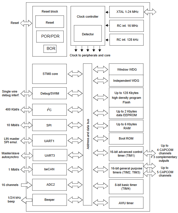
STM8S208RB Block Diagram

STM8S208RB Application
- Consumer Electronics: STM8S208RB is used in products like home appliances and toys, where low-power and simple control are necessary.
- Automotive Applications: It’s applied in automotive systems for tasks like lighting control and sensor interfacing.
- Industrial Control: The microcontroller is used for controlling machines and automation processes.
- Smart Home: It’s used in devices like thermostats and smart lighting systems.
- Portable Devices: Given its low power consumption, it is ideal for battery-operated devices.
- IoT: It can be found in IoT devices, particularly those requiring efficient processing and connectivity.
- Security: STM8S208RB is often used in alarms, security cameras, and related systems.
- Health: It also finds use in medical monitoring systems.
IAR Project: GPIO LED Blinking Example on STM8S208RB
By following the steps below, you should be able to successfully implement the GPIO LED blinking example on the STM8S208RB using the ST Standard Peripheral Library and the IAR compiler. This example can serve as a starting point for more complex applications involving GPIO control and peripheral initialization.
Required Tools and Resources:
- ST STM8S/A Standard Peripheral Library
- IAR Compiler for STM8
- STM8S208RBT6 Development Board
LED Pin Configuration
In this example, the onboard LEDs are connected to PC6 and PC7 pins of the STM8S208RB microcontroller.
					#define LED_GPIO_PORT  ((GPIO_TypeDef *)GPIOC)
#define LED_GPIO_PINS  (GPIO_PIN_7 | GPIO_PIN_6 | GPIO_PIN_3)

#define  LED1_ON()    GPIO_WriteLow(GPIOC , GPIO_PIN_7)  // Turn LED1 ON
#define  LED1_OFF()   GPIO_WriteHigh(GPIOC , GPIO_PIN_7) // Turn LED1 OFF
#define  LED1_TOGGLE() GPIO_WriteReverse(GPIOC , GPIO_PIN_7) // Toggle LED1

#define  LED2_ON()    GPIO_WriteLow(GPIOC , GPIO_PIN_6)  // Turn LED2 ON
#define  LED2_OFF()   GPIO_WriteHigh(GPIOC , GPIO_PIN_6) // Turn LED2 OFF
#define  LED2_TOGGLE() GPIO_WriteReverse(GPIOC , GPIO_PIN_6) // Toggle LED2
In this code:
- LED1 is controlled using PC7, and LED2 is controlled using PC6.
- The functions
LED1_ON(),LED1_OFF(), andLED1_TOGGLE()control the state of LED1, whileLED2_ON(),LED2_OFF(), andLED2_TOGGLE()control LED2.
Main Program Code
The following is the main program to initialize the LEDs, toggle them, and introduce a delay between each toggle.
					#include "stm8s.h"
#include "led.h"
#include "delay.h"

/* Private function prototypes -----------------------------------------------*/
void LED_Init(void);  // Function to initialize the LED GPIO pins

/* Private functions ---------------------------------------------------------*/

// Function to initialize GPIO pins for the LEDs
void LED_Init(void)
{
    GPIO_Init(LED_GPIO_PORT, LED_GPIO_PINS, GPIO_MODE_OUT_PP_LOW_FAST); // Configure the GPIO pins as push-pull output, low speed
}

// Software delay function
void Delay(uint16_t nCount)
{
    while (nCount != 0)
    {
        nCount--;
    }
}

void main(void)
{
    // Configure the internal clock to 16 MHz
    CLK_SYSCLKConfig(CLK_PRESCALER_HSIDIV1);  // No prescaler; system clock = 16 MHz

    LED_Init();  // Initialize the GPIO pins for LEDs

    while (1)
    {
        // Toggle LEDs on PC6 and PC7 every 1 second
        GPIO_WriteReverse(LED_GPIO_PORT, (GPIO_Pin_TypeDef)LED_GPIO_PINS);
        delay_ms(1000);  // Delay for 1000 ms (1 second)
    }
}

#ifdef USE_FULL_ASSERT

// Function to report assert failures
void assert_failed(u8* file, u32 line)
{
    // Optionally, report the file and line number
    while (1)
    {
    }
}
#endif
Delay Function
Below is the delay function source file (delay.c) that provides both microsecond and millisecond delay functions.
					#include "delay.h"

// Function to create a delay of microseconds
void delay_us(unsigned int nCount)   // Delay in microseconds for 16 MHz clock speed
{
    nCount *= 3;  // Adjust for the system clock speed (16 MHz)
    while (--nCount);  // Decrement nCount until it reaches zero
}

// Function to create a delay of milliseconds
void delay_ms(unsigned int ms)
{
    unsigned int x, y;
    for (x = ms; x > 0; x--)  // Loop for each millisecond
        for (y = 3147; y > 0; y--);  // Inner loop for delay approximation
    __asm( "nop" );  // No operation (to adjust the delay)
    __asm( "nop" );  // No operation (to adjust the delay)
}
Explanation of Delay Functions:
- delay_us: Provides a delay in microseconds. The delay duration is adjusted by multiplying the input value by 3 to match the 16 MHz system clock speed.
- delay_ms: Provides a rough delay in milliseconds using nested loops. This method is suitable for simple timing needs, but for more precision, hardware timers should be used.
Project Setup and Compilation Steps
Download and Set Up STSW-STM8069:
- Ensure that you have downloaded the STM8S Standard Peripheral Library (STSW-STM8069) version 2.3.1 from ST’s official website.
- Include the appropriate header files from the library, such as
stm8s.h,stm8s_gpio.h, etc., in your project.
IAR Compiler Setup:
- Open IAR Embedded Workbench and create a new project for STM8S208RB.
- Select the correct device (STM8S208RB) and ensure the toolchain is configured for STM8.
- Add the necessary source files:
main.c,led.c,delay.c, etc. - Include the STM8S Standard Peripheral Library in your project. Make sure that the correct paths to the library files are set.
Compile and Flash:
- Compile the project in IAR. Resolve any compile-time errors if necessary.
- Flash the firmware onto your STM8S208RB development board using an appropriate programmer/debugger (e.g., ST-Link).
Testing and Debugging:
- After flashing the code, observe the LEDs on PC6 and PC7. The LEDs should blink with a 1-second interval.
- Use a debugger or serial output (if available) to inspect the behavior of the GPIO pins and verify the functionality of the delay functions.
Additional Suggestions and Notes
Using Timers for Delay: The software-based delay is simple but inefficient for more complex applications. For more precise and efficient delays, consider using hardware timers instead of software delays.
Power Optimization: If your application requires low power consumption, you might want to explore low-power modes of the STM8S208RB chip, especially when the system is idle (such as during LED blinking).
Debugging: You can set breakpoints in the code to step through the program and monitor the values of variables. This is particularly useful to check the timing of delays and the state of GPIO pins.
GPIO Pin Definitions: Ensure that the
LED_GPIO_PORTandLED_GPIO_PINSdefinitions match the actual pinout of your development board. For example, confirm that PC6 and PC7 are the correct pins for your LEDs.


