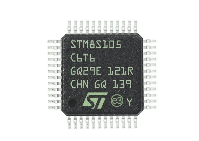
The STM8S105C6 microcontroller is a robust, reliable, and cost-effective solution for embedded system designs, offering excellent performance, flexibility in peripheral support, and low power consumption. Whether for industrial, automotive, or consumer electronics applications, this microcontroller provides all the essential features needed to develop high-quality embedded products. In this article, we’ll introduce the STM8S105C6 microcontoller and how to program it by UART.
STM8S105C6 Introduction
The STM8S105C6 is a member of the STM8S family of microcontrollers, manufactured by STMicroelectronics. It is based on the STM8 core architecture and is designed for a wide range of applications in embedded systems, such as automotive, industrial control, home automation, and consumer electronics. The STM8S105C6 combines high performance, low power consumption, and a wide variety of peripherals, making it a versatile and cost-effective solution for many embedded applications.
Key Features of STM8S105C6
- Core: 8-bit STM8 core with high-speed processing capability.
- Clock Speed: The microcontroller operates at a maximum frequency of 16 MHz.
- Memory:
- Flash Memory: 32KB of in-system programmable Flash memory.
- RAM: 2KB of SRAM for data storage.
- Peripherals:
- I/O Ports: 16 general-purpose I/O pins.
- Timers: 2 general-purpose 16-bit timers, 1 watchdog timer.
- Communication Interfaces: UART (Universal Asynchronous Receiver-Transmitter) for serial communication, SPI (Serial Peripheral Interface), I2C (Inter-Integrated Circuit).
- Analog Features: 1 ADC (Analog-to-Digital Converter) with 8 channels, 10-bit resolution.
- PWM (Pulse Width Modulation): Capable of generating PWM signals for controlling motors or LEDs.
- Voltage Range: Operates within a voltage range of 2.95V to 5.5V, making it suitable for various power supply configurations.
- Low Power Consumption: Optimized for low-power operation, with several power-saving modes such as Sleep, Wait, and Halt.
- Development Tools: The STM8S105C6 is supported by a variety of development tools, including STMicroelectronics’ STVD (STM8 Development Environment), IAR Embedded Workbench, and other third-party IDEs (Integrated Development Environments).
- Package Options: The STM8S105C6 is available in a 32-pin LQFP (Low-profile Quad Flat Package), making it compact and easy to integrate into a wide range of designs.
STM8S105C6 Specifications
| Feature | Specification |
|---|---|
| Core | 8-bit STM8 core |
| Clock Speed | Up to 16 MHz |
| Flash Memory | 32KB (in-system programmable) |
| SRAM | 2KB |
| Voltage Range | 2.95V to 5.5V |
| Timers | 2x 16-bit general-purpose timers |
| Watchdog Timer | Yes |
| Communication Interfaces | UART, SPI, I2C |
| Analog Features | 8-channel, 10-bit ADC |
| PWM Channels | Yes |
| Operating Temperature Range | -40°C to 125°C |
| Package Type | 32-pin LQFP |
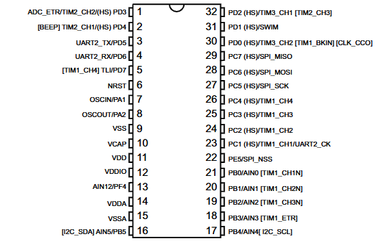
STM8S105C6 Pinout
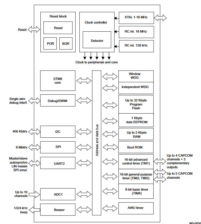
STM8S105C6 Block Diagram
How to Program STM8 via UART
In addition to using the STLINK programmer, the STM8S105C6 microcontroller can be programmed through its UART interface with the Flash Loader Demonstrator software to write compiled programs to the microcontroller.
Required Tools:
- STVD-STM8 (Version: 42.0.0)
- IAR Embedded Workbench IDE (Version: 9.40.2)
- Flash Loader Demonstrator (Version: 2.8.0)
- STM8S105C6 Development Board
For a detailed explanation of the programming process, we have divided it into three steps:
1. Enabling the BootLoader
Before programming via UART, the “BootLoader Enable” option needs to be activated on the chip. By default, this is enabled on new chips. However, once a program is flashed, it gets disabled. There are two methods to enable the BootLoader:
- Using the ST LINK and STVP (ST Visual Programmer) software to modify the chip’s OPTION BYTE.
- Modifying the OPTION BYTE through a program.
Using ST LINK to Modify OPTION BYTE
First, connect the ST LINK, STM8 development board, and the computer, and open the STVP (ST Visual Programmer) software. STVP is automatically installed when the STVD development environment is set up. It is a full-featured graphical programming tool used to program the flash memory of ST microcontrollers, allowing you to read, edit, and write to the STM8’s FLASH, EEPROM, and OPTION BYTE.
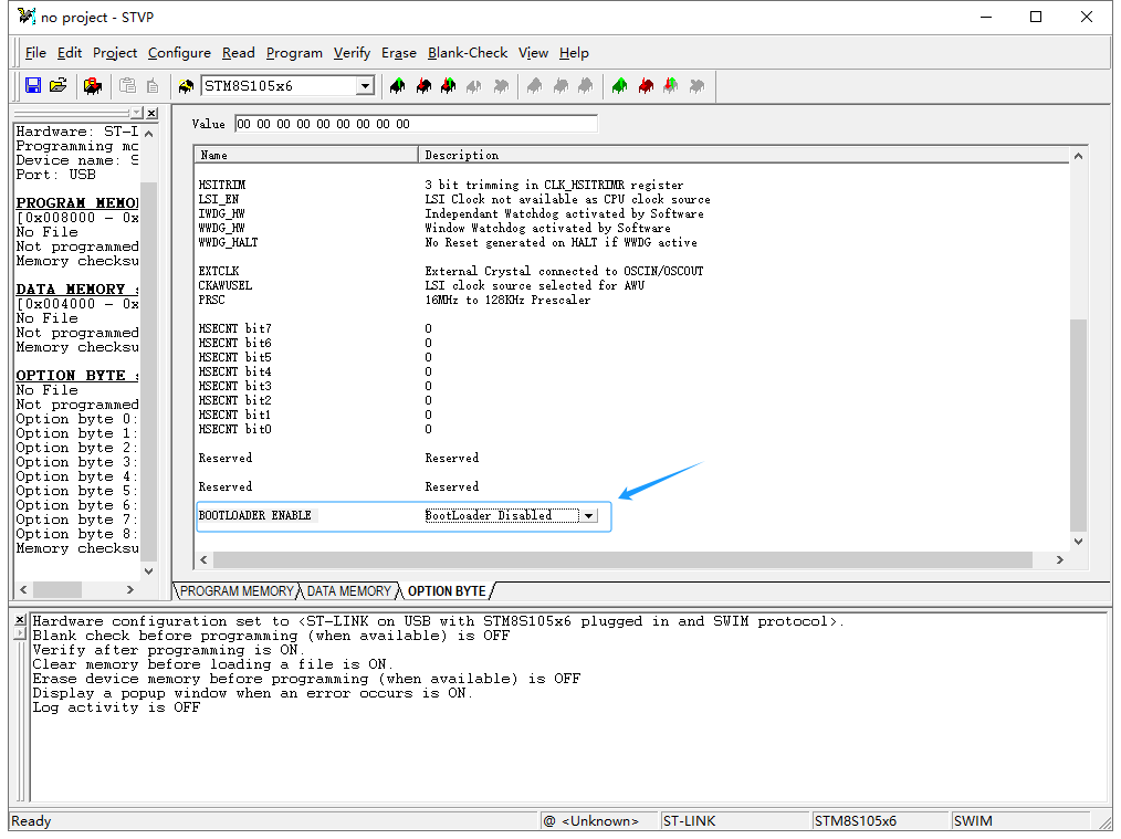
Next, modify the OPTION BYTE to enable the BootLoader. In the STVP software, go to the OPTION BYTE tab and locate the BootLoader option, usually at the bottom of the OPTION BYTE list. Click “BootLoader Disable” and select “BootLoader Enable” from the dropdown menu. After setting this, click “Program Current Tab” or “Program All Tabs” in the toolbar to write the OPTION BYTE to the STM8 microcontroller, thus enabling the BootLoader.
Using a Program to Modify OPTION BYTE
To enable the BootLoader via a program, compile the following code and burn it onto the STM8 using ST LINK:
					FLASH_DeInit();  // Restore FLASH registers to default values
FLASH_Unlock(FLASH_MEMTYPE_DATA);  // Unlock data EEPROM

// Program OPTION BYTE
FLASH_ProgramOptionByte(0x487e, 0x55);
FLASH_ProgramOptionByte(0x487f, 0xAA);
2. Development Environment Setup
STVD Development Environment
After compiling with the Cosmic compiler in STVD, it will generate a *.s19 file by default. This file can be directly flashed into the STM8 microcontroller using the Flash Loader Demonstrator software. The software also supports flashing *.hex and *.bin files. Below is how to configure STVD to generate these three formats.
- Open the STVD project file and go to the Project Properties.
- Select the Post-Build tab as shown below.
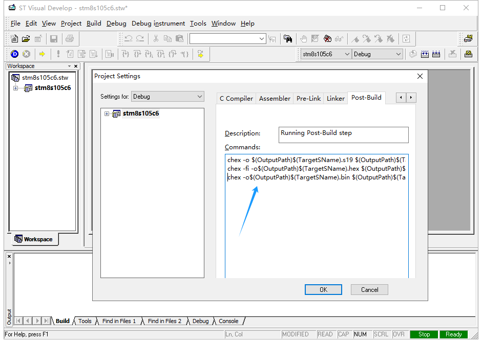
In the Commands text box, add the following commands after the existing one:
					chex -fi -o$(OutputPath)$(TargetSName).hex $(OutputPath)$(TargetSName).sm8
chex -o$(OutputPath)$(TargetSName).bin $(OutputPath)$(TargetSName).sm8
Click OK to confirm. After compiling, three different file formats will be generated.
IAR Development Environment
The IAR development environment does not use the Cosmic compiler, so it cannot generate *.s19 files. However, it can generate the other two formats. To configure this in IAR:
- Open the IAR project file and go to the Project Properties.
- Select the Output Converter tab.
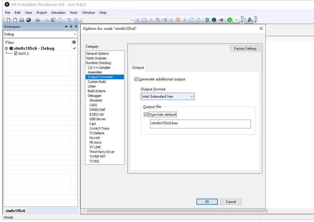
Next, check the Generate additional output option. In the Output format dropdown, select Intel extended to generate a *.hex file or Binary to generate a *.bin file. Select the Override default option and input the desired file name and format in the text box. Click OK to confirm. After compiling, the chosen file format will be generated.
3. Programming with Flash Loader Demonstrator
Flash Loader Demonstrator is an ISP download tool from ST, which can be used to program STM32 or STM8 microcontrollers through UART. It supports flashing *.s19, *.hex, and *.bin files. Below is how to use it to program the STM8 microcontroller:
- Connect the STM8 development board to the computer via UART and install the Flash Loader Demonstrator software. After installation, open the software, and the main interface will appear.
- Select the appropriate UART port connected to the STM8 development board under the Port Name dropdown.
- In the Echo dropdown, select Echo Mode for STM8S or Disable for STM8L.
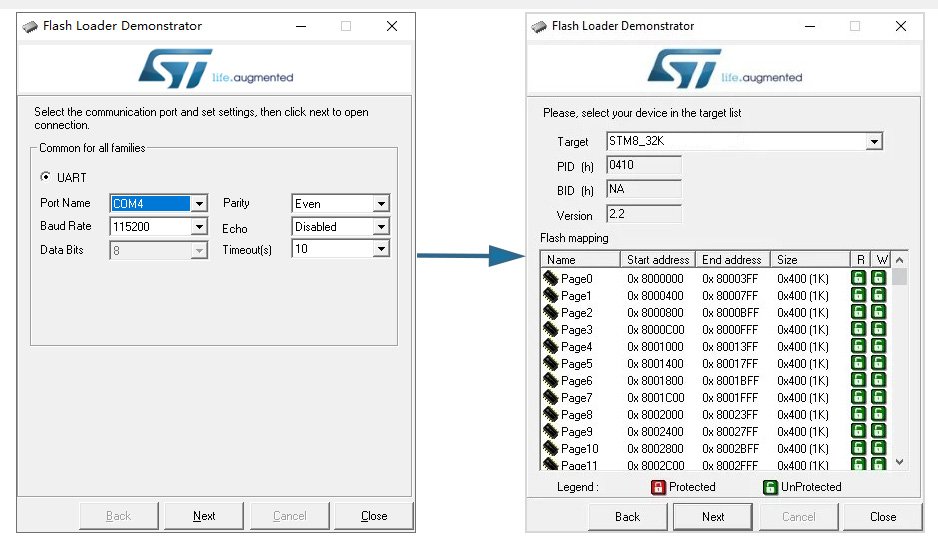
Next, reset the STM8 development board and quickly click the Next button. You must click within one second to ensure the Flash Loader Demonstrator can receive data from the STM8’s BootLoader. If successful, the software will move to the STM8 device selection screen.
The device type is determined by the STM8 chip and its internal FLASH size. For STM8S microcontrollers, select STM8_XXK from the dropdown. For STM8L, select STM8L_XXK. Based on the STM8S105C6 on our development board, which has 32KB of internal FLASH, choose STM8_32K from the dropdown.
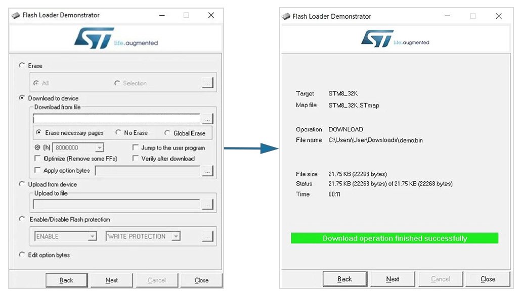
Then, click Next, and the software will prompt you to select the file to be flashed. In the Download from file box, browse to the file path of the program to be flashed. Click Next, and the file will be written to the STM8 microcontroller’s internal FLASH. Upon successful flashing, the software will display the message “Download operation finished successfully.”
Finally, click Close to exit the Flash Loader Demonstrator software. Reset the STM8 development board, and the microcontroller will run the program according to the defined flow. Note that the program is copied to the FLASH memory, and you need to reset the device for the pointer to jump to the user program and begin execution. If you want the program to automatically run after flashing, check the Jump to the user program option.
Typical Applications
- Automotive: Control units, sensors, and displays.
- Industrial: Process control, automation systems, and motor controllers.
- Consumer Electronics: Smart devices, remote controls, and small appliances.
- Home Automation: Smart home systems, energy meters, and security systems.

