Radio frequency (RF) circuits are electronic devices that use RF signals to transfer information between different devices. An RF circuit has two primary functions: receiving signals from an antenna and transmitting them to another device. In this article, we explore what an RF circuit is and how it works. We discuss the main parts of an RF circuit, its different applications, and some common types you may come across if you’re interested in designing your own circuits.
What is an RF Circuit?
An RF circuit (radio frequency circuit) is an electronic device that uses RF signals to transfer information between different devices. An RF circuit has two primary functions: receiving signals from an antenna and transmitting them to another device. RF circuits are commonly found in wireless communication devices. For example, cell phones and WiFi routers use RF circuits to send signals between devices. RF circuits usually operate at very high frequencies. This means that their signals are traveling very fast (usually between 300 MHz – 30 GHz). This is why you can only hear static when you hold a device nearby an RF circuit.
How Does RF Circuit Work?
The RF chip architecture includes two parts: the receiving channel and the transmitting channel. The transmitter is the part of the circuit that creates the electromagnetic wave. The receiver is the part of the circuit that transforms that wave back into an electrical signal. A signal is first received by the antenna, which is then sent through the transmitter to be transformed into an electromagnetic wave. Finally, the signal travels through the receiver, where it is transformed back into an electrical signal. The receiver is often connected to a device (like a speaker) so that the information can be heard or displayed.
receiving circuit
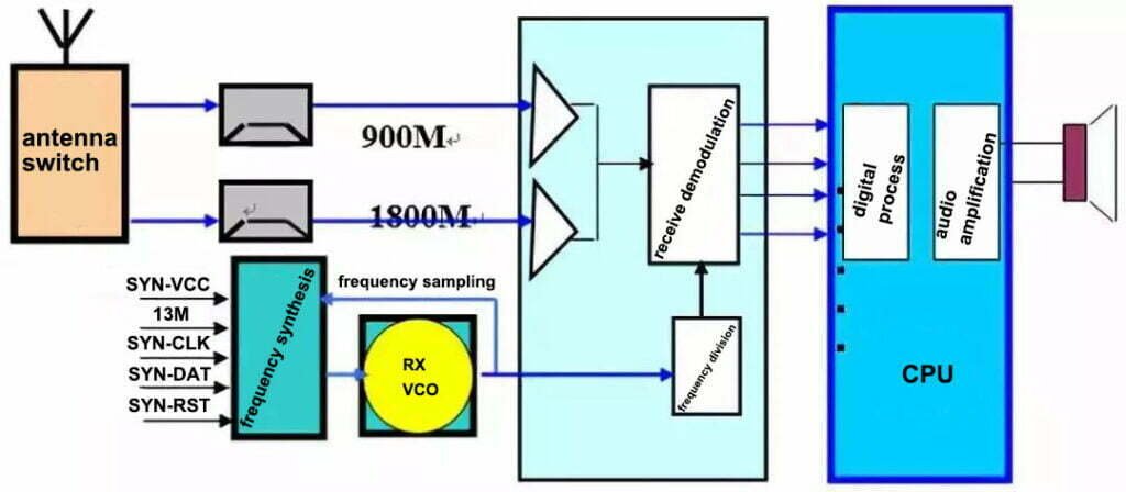
The receiving circuit is composed of antenna, antenna switch, filter, low noise amplifier, receiver demodulator, etc.

First, the receiver transforms that electromagnetic wave into an electrical current. Then, the electrical current travels through the filter, and amplifier to create a feedback signal. Next, the feedback signal is then sent to a demodulator that transforms that signal into baseband information such as RXI-P, RXI-N, RXQ-P, RXQ-N. Finally, it is sent to the logic audio circuit for further processing.
transmitting circuit
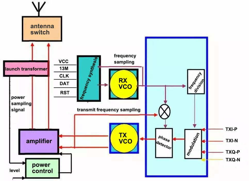
The primary function of an RF transmitter is to transform your information into an electromagnetic wave so that it can be sent to another device through an antenna. An RF transmitter uses electricity to create electromagnetic waves.
RF transmitter Structure
The fundamental components of an RF transmitter are voltage-controlled oscillator (VCO), amplifier, phase detector, and modulator. The oscillator produces an alternating current at a certain frequency, which is determined by the number of oscillations per second. This is known as the carrier frequency. The amplifier amplifies the signal so that it can be sent through the antenna. The modulator is used to control the amplitude, frequency, and phase of the carrier wave, which allows for the transmission of data.

Working methods
When connected to an antenna, the radio frequency (RF) transmitter produces an electromagnetic signal in range of the electromagnetic spectrum. It works by generating a carrier wave at the desired frequency and then modulating it with an input signal, such as speech or music. The carrier wave is then amplified and sent out through the antenna. The antenna broadcasts the carrier wave, and the signal is picked up by the receiver. The receiver then demodulates the signal and extracts the data from it. This process is known as modulation and demodulation.
RF Circuit and Their Importance
An RF circuit is any electrical circuit that is designed to operate at radio frequencies. RF circuits are used in many consumer and industrial products, such as remote controls. RF circuits are also used in wireless networks, such as WiFi networks. A diagram of an RF circuit is called a circuit diagram or a schematic diagram. An RF circuit diagram shows the electrical components used in the circuit as well as their connections. Before designing an RF circuit, engineers must first understand the characteristics of radio frequencies, including impedance and the propagation of radio waves. Engineers must also understand the design tools that are used to design RF circuits, such as circuit analysis and circuit simulator programs. RF circuits are designed to operate at high frequencies, and so they must be properly shielded to prevent interference with nearby circuits. RF circuits also require proper grounding to prevent interference with other electrical systems in buildings.
Common Applications of RF Circuits
RF circuits are commonly found in wireless communication devices like radios and cell phones. The circuits are usually used to share information between devices in a short distance. For example, a WiFi router may use an RF circuit to send and receive information to nearby computers. RF circuits may also be used in long-distance communication by bouncing off a satellite. For example, ham radio operators use RF circuits to send and receive information while they are in space. These are the common systems or devices that use RF circuits.
– Wireless communication systems:
- radio receivers and transmitters
- satellite communication
- radios and cell phones
- broadcast television systems
– Radar systems:
- antenna systems
- remote sensing systems
- distance monitoring
– Automotive applications:
- Navigation systems
- GPS and navigation systems
- automotive collision avoidance systems
– Security systems:
- smoke alarms
Smart home systems:
- surveillance cameras
- household gas meters
- electricity meters
Final Words
An RF circuit is an electronic device that uses RF signals to transfer information between different devices. An RF circuit has two primary functions: receiving signals from an antenna and transmitting them to another device. This communication is usually done on a long-distance scale, since RF circuits use high frequencies to transmit information. If you’re interested in designing your own circuits, it’s important to understand how they work. This article has explored what an RF circuit is and how it works.


