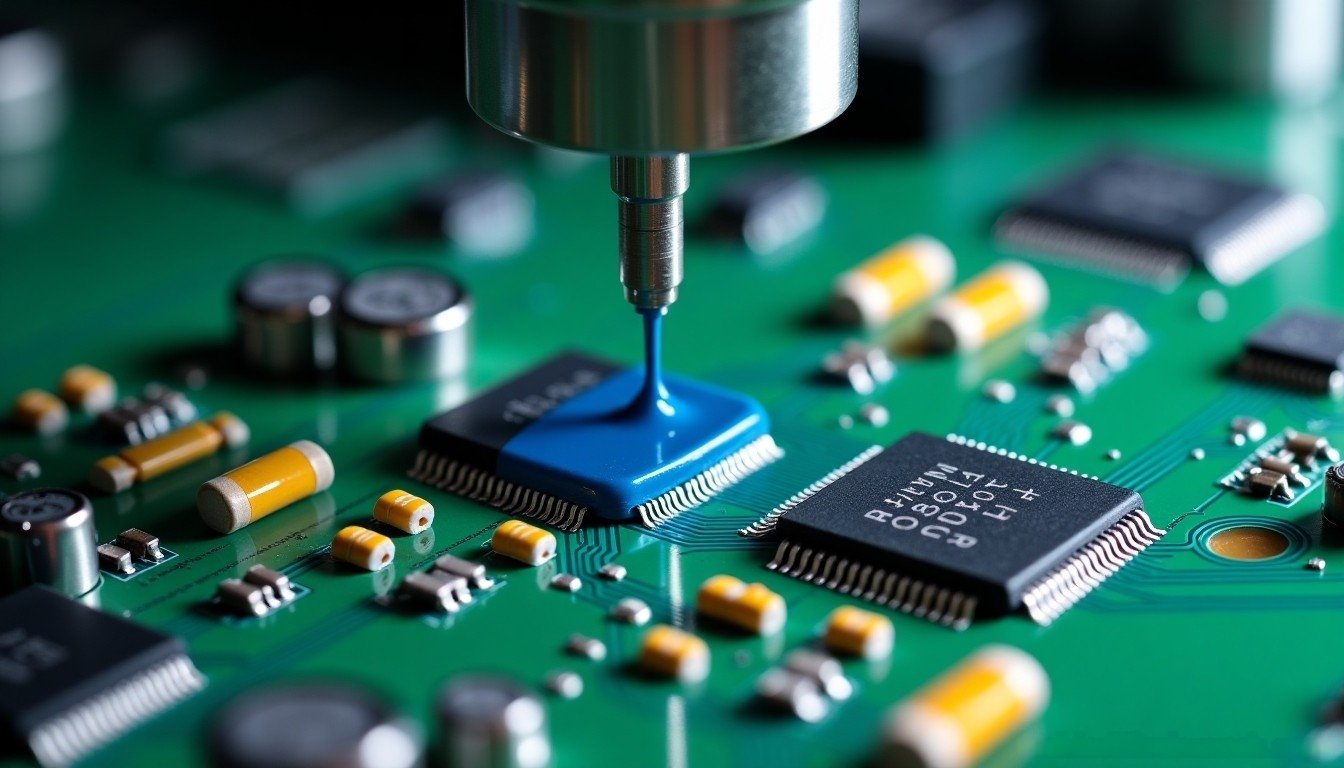
DC Motor Speed Formula
At first, let’s introduce the formula of DC motor speed:
n=(U-IR)/KΦ
Where “n” is the motor speed (rpm/min), “U” is the armature voltage, “I” is the armature current, “R” is the resistance of the armature circuit, “Φ” is the excitation flux, “k” is the induced electromotive force constant. It can be seen that the DC motor The rotational speed of the motor is related to U, R, and Φ, so we can change its rotational speed by adjusting these variables.
- Change the Supply Voltage (U)
- Change the Circuit Resistance (R)
- Change the Magnetic Flux (Φ)
Method 1: Change the supply voltage (U)
Changing the voltage is mainly to reduce the armature voltage from the rated voltage down, and change the speed from the rated speed of the motor down, which is a constant torque speed regulation method. This method is the best for systems that require stepless and smooth speed regulation within a certain range. The time constant encountered in the change of the armature current is small, and it can respond quickly, but it needs a large-capacity adjustable DC power supply.
Features:
- Wide range of speed regulation, called stepless speed regulation.
- There is no additional energy loss, and the hardness of the mechanical properties remains unchanged after the voltage is reduced, and the stability is good.
- The speed can only be adjusted down, not up.
- The required equipment is more complicated and the cost is higher.
Method 2: Change the Circuit Resistance (R)
The method of speed regulation by connecting resistors in series outside the armature circuit of the motor has simple equipment and convenient operation. But it can only have step speed regulation, the smoothness of speed regulation is poor, and the mechanical characteristics are soft; a large amount of electric energy is consumed in the speed regulation resistor. There are many disadvantages of changing the resistance speed regulation, and it is rarely used at present.
Features:
- The required equipment is relatively simple and low in cost, and it is widely used in low-power DC motors.
- The speed can only be adjusted down, which is a step-by-step speed regulation, and the characteristic curve is soft.
- There is a large energy loss in the speed regulating resistor, and the economic performance is poor.
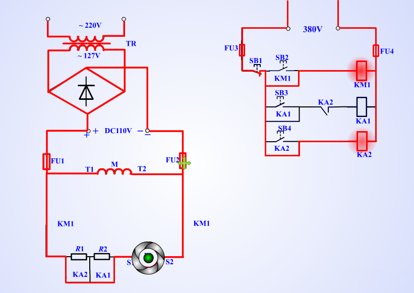
Schematic Diagram:
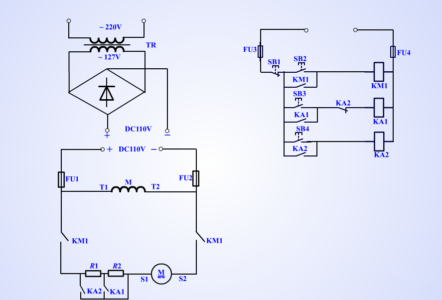
In the circuit of a DC motor, we can achieve different speeds by connecting different resistors in series. Its circuit schematic diagram consists of three parts: rectifier circuit, main circuit and control circuit. The power supply of the main circuit is AC 220 volts, and the access power of the control circuit is 380 volts. In addition, there are three electrical components on the circuit, including a KM1 and 2 intermediate relays.
Low Speed Mode:
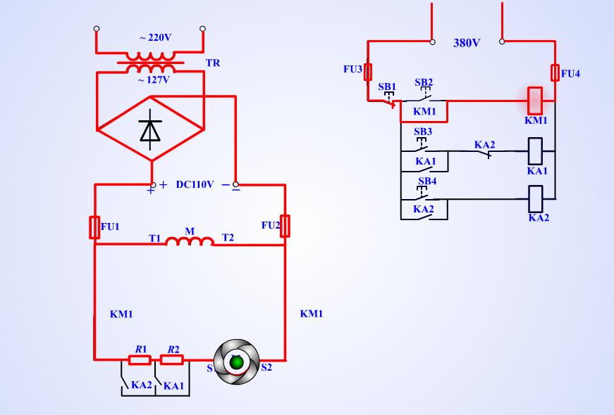
The power supply is AC 220 volts, which is converted to AC 127 volts through a transformer, and then converted to DC 110 volts through a rectifier circuit. Three button switches control three speeds. When SB2 is pressed, the contactor KM1 is self-locked. At this time, the motor is connected with two resistors R1R2 in series, which is the lowest speed state.
Middle Speed Mode:
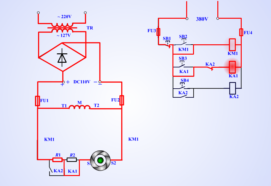
If you want to increase the speed, you can press the button switch SB3, then the relay KA1 will lock itself. At the same time, its normally open point will be closed, and the current skips R2 and directly connects to the motor to achieve acceleration.
High Speed Mode:
To switch to the high speed mode, press the button switch SB4. At this time, KA2 is self-locking. At the same time, its normally closed point is opened to power off KA1, and the normally open point is closed to directly skip the R1 resistor.
Method 3: Change the Magnetic Flux (Φ)
Changing the magnetic flux can realize stepless smooth speed regulation, but it can only weaken the magnetic flux, and adjust the speed upward from the rated speed of the motor, which is a constant power speed regulation method. The time constant encountered when the armature current changes is much larger, and the response speed is slower. But the required power supply capacity is small.
Features
- The speed regulation is carried out in the excitation circuit, the energy loss is small, and the control is convenient.
- Smooth stepless speed regulation, but the speed can only be adjusted upwards from the rated speed, which is often used as an auxiliary speed regulation.
- The range of speed adjustment is narrow, and when ф decreases too much, it is difficult to change direction and the spark is large.


