STM32F405RGT6 Introduction
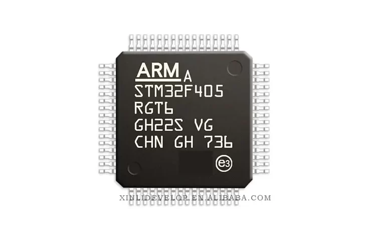
The STM32F405RGT6 microcontroller is an advanced Arm® Cortex®-M4-based 32-bit MCU. It features a powerful 32-bit Cortex®-M4 core that operates at a maximum frequency of 168 MHz and offers digital signal processing (DSP) instructions, as well as six-channel DMA and a rich set of peripherals. It also offers advanced power management capabilities, including dynamic voltage scaling (DVS).
Core Features
- High-performance 32-bit ARM® Cortex®-M4 core
- Up to 168 MHz maximum frequency
- DSP instructions and six-channel DMA
- Up to 1 MB of Flash memory
- Up to 192 KB of SRAM
- Advanced power management features
- Dynamic voltage scaling (DVS)
- Real-time clock (RTC)
- External memory interface
- Multiple serial interfaces
- USB 2.0 interface
- Advanced motor control peripherals
- LCD controller
- 12-bit ADC
- Up to four 16-bit timers
- Two watchdog timers
Advantages of STM32F405RGT6
Memory Map
The STM32F405RGT6 features up to 1 MB of on-chip Flash memory and up to 192 KB of SRAM. It also offers an external memory interface for external Flash and SRAM.
Power Management
The STM32F405RGT6 features a wide range of advanced power management features, including dynamic voltage scaling (DVS) and a low-power RTC. The DVS feature allows users to lower the voltage and frequency of the device, which reduces power consumption and increases the power efficiency of the device.
Peripherals
The STM32F405RGT6 features a wide range of peripherals, including 12-bit ADC, four 16-bit timers, two watchdog timers, and multiple serial interfaces, such as USB 2.0, UART, and I2C. It also features advanced motor control peripherals and an LCD controller.
STM32F405RGT6 Programming Header and First-Power Checks
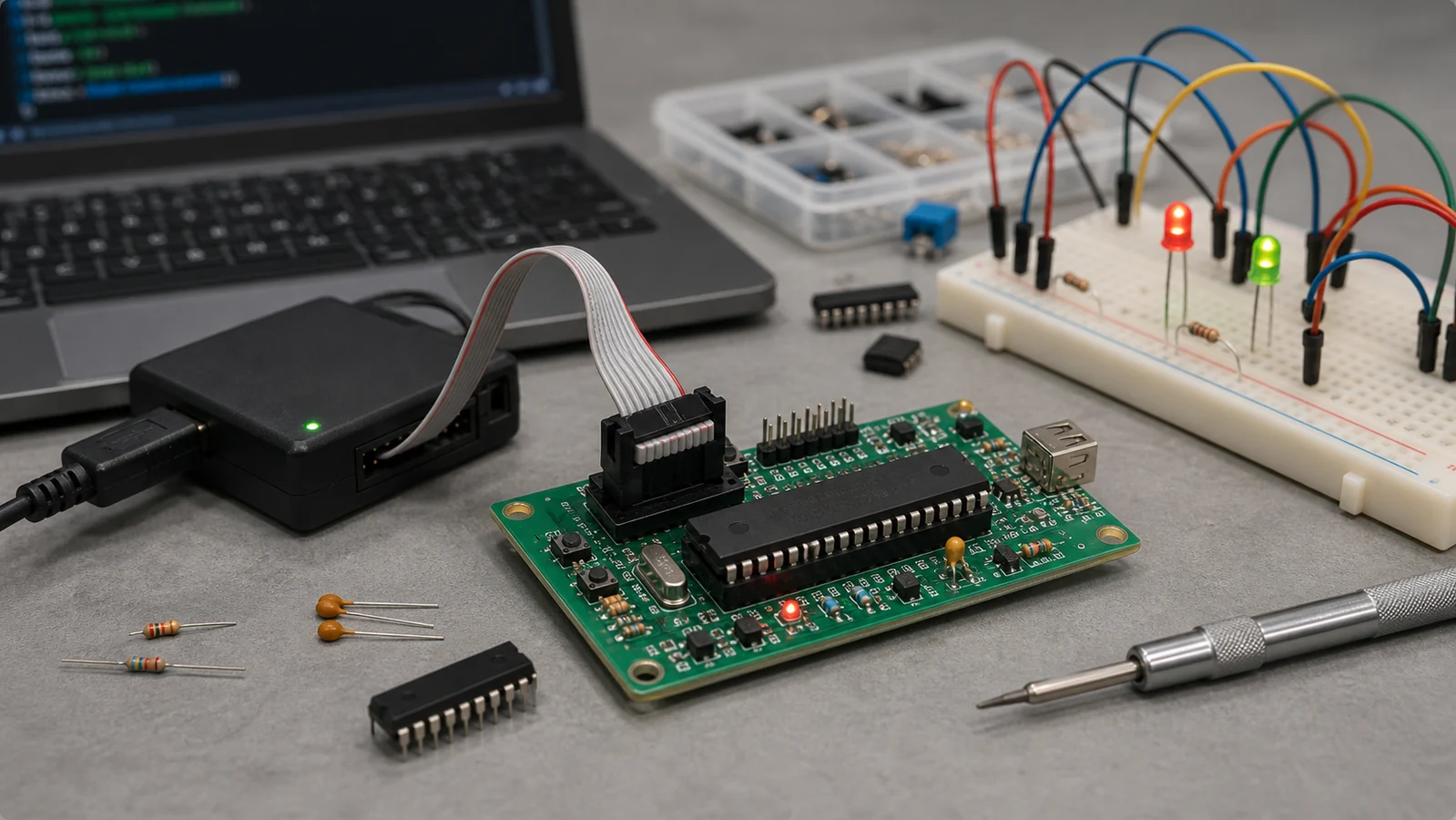
Use the exact LQFP64 STM32F405RGT6 pinout when building the programming hardware rather than relying on a generic STM32F4 drawing. A reliable SWD connection depends on a correctly powered core, the regulator capacitor network, defined boot state, and short signal returns as much as on the two debug signals. At first power, use current limiting, verify all rails, reset, and both VCAP nodes, then connect at a conservative SWD clock and read the device identifier. Program a minimal image before enabling PLLs, external buses, or high-current peripherals.
- Supply pins: connect every
VDD/VSSand analog supply pair shown in the datasheet, with a local bypass at each supply group and suitable bulk capacitance. - Regulator nodes: fit the specified capacitors on
VCAP1andVCAP2, route them tightly, and do not use these nodes to power external loads. - SWD header: provide
PA13/SWDIO,PA14/SWCLK, target-voltage reference, ground, and preferablyNRST; addPB3/SWOonly when trace output is needed. - Boot definition: bias
BOOT0to the normal application state while retaining a controlled way to invoke the system bootloader. - Signal integrity: keep SWD clock and data short, place a ground return beside them, avoid strong external pulls, and never apply a programmer voltage outside the powered target rails.
How to Program the STM32F405RGT6?
The STM32F405RGT6 is a powerful Cortex-M4 processor with a range of peripheral options. It is a popular microcontroller and with the right development tools can be programmed to do a variety of tasks. Here we will look at the methods and steps needed to successfully program the STM32F405RGT6.
What do I Need?
Before attempting to program the STM32F405RGT6 you will need the following:
– A development board with the STM32F405RGT6 processor.
– A computer with the correct driver and software installed.
– A USB cable to connect the board to your computer.
– A programmer (e.g. STM32CubeProgrammer).
Steps to Program
Once you have all the necessary equipment, you can begin programming the STM32F405RGT6:
1. Connect the development board to your computer via the USB cable.
2. Install the appropriate drivers and software on your computer.
3. Open the STM32CubeProgrammer and select the board (STM32F405RGT6) from the list.
4. Download the program code onto your board.
5. Verify the program code is correct.
6. Burn the program code onto the board.
7. Disconnect the board from your computer.
Your STM32F405RGT6 is now programmed and ready to be used. With the correct development tools, you can now begin creating your own applications for the board.