Atmega128 /328 is a powerful microcontroller that is used in a variety of application fields. It is a highly integrated 8-bit microcontroller with a wide range of peripherals and features. In this blog post, we will take a look at the different features of the Atmega128 / 328, its pin configuration, programming techniques, and applications. We will also discuss the advantages of the Atmega128 / 328 microcontroller over other microcontrollers, and provide some best practices for working with it.
What is Atmega128 / 328?
Atmega128 / 328 is an 8-bit microcontroller manufactured by Atmel Corporation. It is based on the AVR architecture, and is one of the most popular microcontrollers used in embedded systems. It is available in various packages and configurations, including a 40-pin PDIP, a 44-pin TQFP, and a 64-pin VQFP. The Atmega128 / 328 is based on the RISC architecture and has a wide range of peripherals, including an 8-channel 10-bit A/D converter, three 16-bit timers, a serial port, and an SPI port. It has a total of 128Kbytes of program memory and 2Kbytes of EEPROM.
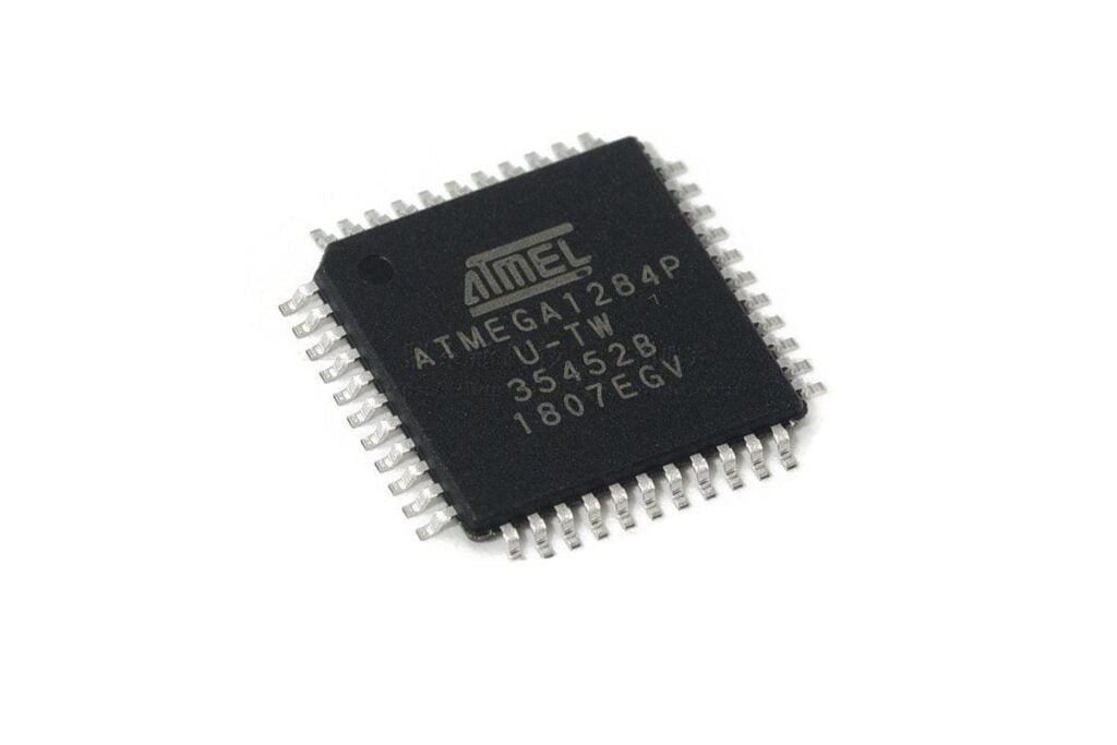
Overview of Atmega128 / 328
Features
Atmega128 / 328 has a wide range of capabilities, making it a versatile and powerful microcontroller. It has a 16-bit RISC architecture, which allows it to execute instructions quickly and efficiently. It can operate at 8MHz, 16MHz, or 20MHz, making it suitable for a wide range of applications. The Atmega128 / 328 also has a wide range of peripherals, including an 8-channel 10-bit A/D converter, three 16-bit timers, a serial port, and an SPI port. It also has 128Kbytes / 328 Kbytes of program memory and 2Kbytes of EEPROM, allowing it to store large amounts of data.
The Atmega128 / 328 is also highly integrated, making it ideal for use in embedded systems. It has an on-chip oscillator, an on-chip reset circuit, and on-chip voltage regulation. It also has an on-chip power-on reset circuit, which ensures that the microcontroller is reset when power is applied. Additionally, the Atmega128 has a wide range of I/O ports, allowing it to interface with a variety of external devices.
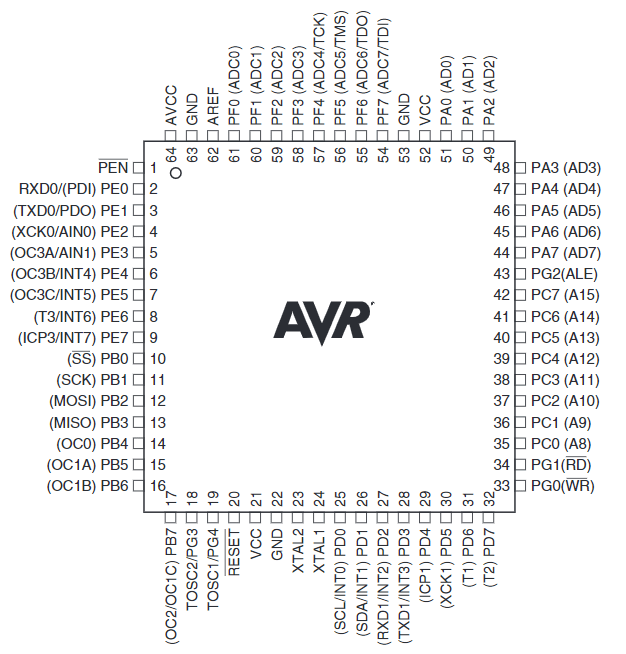
Pin Configuration
Atmega128 / 328 has a total of 64 pins, which are arranged in two rows. The pins are divided into two categories: digital I/O pins and analog I/O pins. The digital I/O pins are used for controlling digital signals, while the analog I/O pins are used for controlling analog signals. The Atmega128/ 328 also has a serial port, an SPI port, and an I2C port.
Applications
- Robotics projects, such as in robotic arms and autonomous robots.
- Communication projects, such as in Bluetooth and Wi-Fi modules.
- Data acquisition systems and embedded systems for data logging and control.
- Automotive applications, such as in engine control systems and in-vehicle infotainment systems.
- Consumer products, such as remote controls, digital cameras, and home appliances.
Programming the Atmega128 / 328
The Atmega128 / 328 IC can be programmed using either C or assembly language. It has a wide range of features that make it easy to program, including a wide range of I/O ports, an on-chip oscillator, and an on-chip voltage regulator.
If you’d like to program the Atmega128 / 328, you will need a programmer. A programmer is a device that is used to transfer the program code from a computer to the Atmega128 / 328. Once the program code is transferred, the IC can be programmed using the appropriate software. All the steps can be devided to 4 parts as below:
- Part 1: Preparing the Necessary Components.
- Part 2: Building Arduino Circuits on a Breadboard.
- Part 3: Burn the bootloader into the Atmega128 / 328 IC.
- Part 4: Programming the Atmega128 / 328 IC.
Part 1: Preparing the Components
Atmega128 / 328: The key component on the breadboard and its pinout diagram is given above.
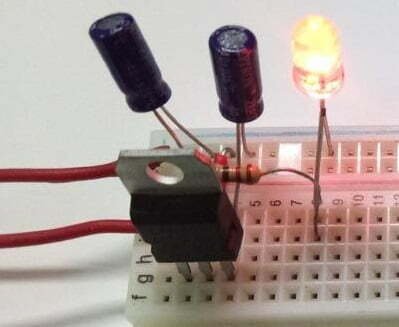
Breadboard (LM7805): A solderless device for connecting electronic components with jumper wires.
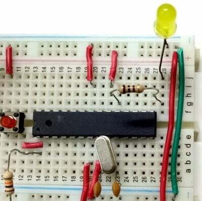
Oscillators (16 MHz): Providing the clocks for IC, connected with Pin 23 and Pin 24.
Capacitor (10uF): Used in the input and output sections of the LM7805 to bypass any AC components to ground.
Wire Jumper: A metal wire connecting two points on a circuit board or breadboards.
Part 2: Building Arduino Circuits on a Solderless Breadboard
Step 1: First, connect the power section as shown in the circuit diagram and test it with the LM7805’s external power supply. It looks like this:
Step 2: Then, connect the microcontroller part as shown in the circuit diagram.
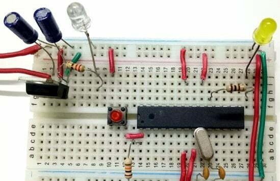
Step 3: Now, use wire jumpers to connect the power supply and the microcontroller section.
Part 3: Burn the bootloader into the Atmega128 / 328 IC
A bootloader is a small piece of executable code stored permanently in the microcontroller’s memory. This takes up less than 1Kb of memory. A bootloader allows the IC to accept code from the computer and place it in the microcontroller’s memory.
When you buy a new Atmega128 / 328 off the market, it doesn’t have a bootloader. Therefore, to program it using the Arduino IDE, you must first upload the bootloader.
To upload the bootloader, we have two methods:
- Using USBasp Programmer
- Using an Arduino UNO board
Compared with the first method, the second method is easier. Because it requires fewer connections and the latest versions of the Arduino IDE are less compatible with USBasp programmers.
So, in this tutorial, we will use the Arduino UNO board to upload the bootloader.
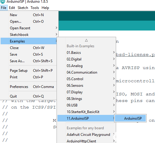
Step 1: Open the Arduino IDE. Go to the menu: File -> Examples -> ArduinoISP. Than choose ArduinoISP.
Step 2: Now, you have to upload this code to your Arduino board. Select com port and board from the tools menu and click the upload button.
Step 3: After completing the upload, disconnect the Arduino board from the computer. And then connecting the Arduino board with the Atmega128 / 328 IC as shown in the picture below.
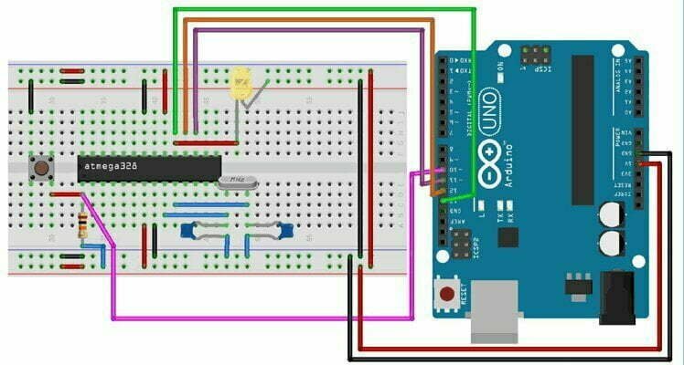
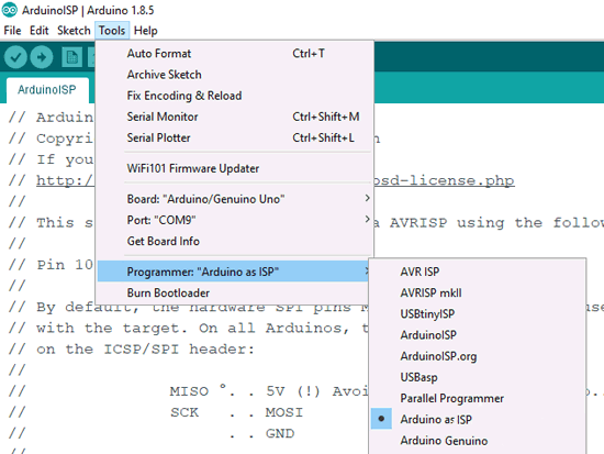
Step 4: Please open the Arduino IDE after you connect the Arduino board with your computer. Next, go to menu: Tools -> Board: “Arduino/Genuin0 Uno” and select the correct port for your board. Then, select Programmer: as “Arduino as ISP”.
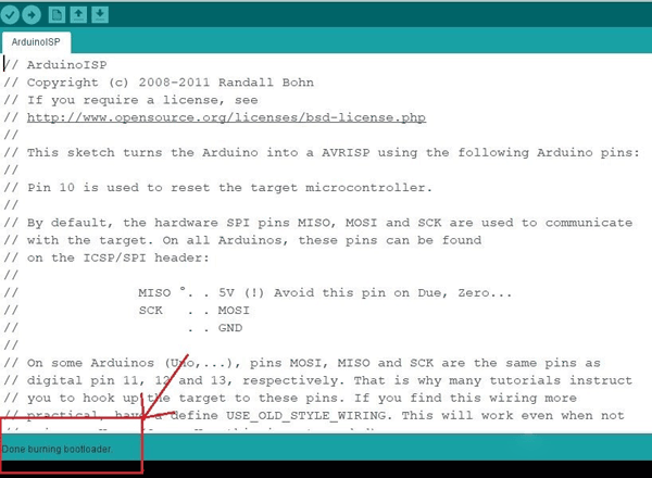
Step 5: Now, go to the Tools menu bar again and click on Burn Bootloader under the Programmer option. After a few seconds, the bootloader is successfully uploaded. If there are any errors with the upload, please check the connection.
Part 4: Programming the Atmega128 / 328 IC
The Arduino Atmega128 / 328 chip can be programmed in different ways, including:
- Use an Arduino board without the Atmega128 / 328 IC.
- Use the USB-to-serial TTL conversion module (FTDI module).
- Use a USBasp programmer (if there’re many connections).
Here, we introduce the first and second ways for programming Atmega128 / 328 IC.
4.1 Programming the Atmega128 / 328 IC Using an Arduino Board
Step 1: Take an Arduino board without Atmega128 / 328 chip. Then connect the Arduino board with our breadboard as shown.
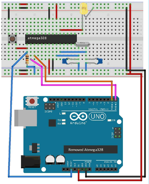
Step 2: Connect the Arduino board with the computer and open the Arduino IDE. Select Arduino Uno from the Board menu in Tools, Programmer as USBasp and the correct com port of the board.
Step 3: We will start by uploading the Blink program. So select the blink program from the examples and hit the upload button.
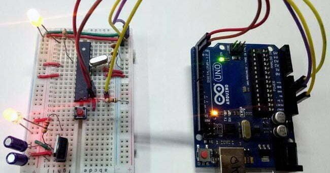
You can now see the LED on the breadboard start blinking.
4.2 Programming the Atmega128 / 328 using a USB-to-Serial Converter
This is the best way to program the Atmega128 / 328 if you don’t have an Arduino board.
Step 1: Set up the USB-to-serial converter connections as follows:
FTDI’s RXD pin -> Atmega128 / 328’s Tx pin (pin 3)
TXD pin of FTDI -> Rx pin (pin 2) of Atmega128 / 328
GND -> GND (pin 8)
5v -> Vcc (pin 7)
Some FTDI modules have a Reset pin, also known as DTR pin, which needs to be connected to the Reset pin (pin 20) of the Atmega128 / 328.
Step 2: Now, connect the FTDI with the computer and open the device manager in the control panel. You will see the Ports section, expand it. If the driver has a yellow mark in front of it, the module driver must be updated.
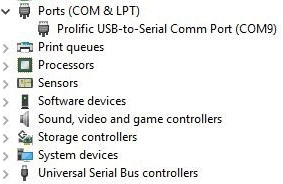
If not marked, note the com port number and open the Arduino IDE. Go to Tools -> Ports -> Select the com you noted down.
Step 3: At the end, we upload the Blink program to our Breadboard Arduino. Go to File -> Examples -> Basics -> Blink. From the Board menu in Tools select Arduino Uno, Programmer as USBasp and the correct board com port.
Then click the upload button.
(Note: If your FTDI module does not have a DTR pin, then press the reset button on the breadboard and hit the upload button. If it says “Compiling sketch…”, press and hold it until “Uploading…” appears and then release the button.)
Now the program will be successfully uploaded into the Arduino Bootloader Atmega128 / 328 chip.
Atmega128 / 328 vs Other Microcontrollers
Atmega128 / 328 is a powerful and versatile microcontroller, but there are other microcontrollers available that may be more suitable for certain applications. For example, the ARM Cortex-M processor is more suitable for applications that require higher performance. The ARM processor is also more power-efficient and is more suitable for low-power applications.
The Atmega128 / 328 is also more expensive than some other microcontrollers. However, it is a powerful and versatile microcontroller, and is suitable for a wide range of applications. Therefore, it is important to consider the application requirements when choosing a microcontroller.
Best Practices for Working with Atmega128 / 328
Atmega128 / 328 is a powerful and versatile microcontroller, and there are a few best practices for working with it. It is important to keep the microcontroller in a static-free environment, as static electricity can damage the microcontroller. It is also important to ensure that the microcontroller is supplied with the correct voltage and that the on-chip voltage regulator is functioning properly. Additionally, it is important to ensure that the on-chip oscillator is functioning properly, as this is used to generate the clock signal.
It is also important to ensure that the development tools are up to date and that the programming code is thoroughly tested before being used in the microcontroller. Additionally, it is important to adhere to the appropriate safety regulations when working with the microcontroller.

