Schematic Diagram Definition
A schematic diagram is a graphical representation of an electrical circuit or system using standardized symbols and notations. It is used to communicate the design of the circuit or system to others, such as engineers, technicians, electricians, or even laypeople. Schematic diagrams can be used for a variety of purposes, such as designing, testing, troubleshooting, or repairing electrical systems. They typically show the arrangement and interconnections of various components, such as resistors, capacitors, diodes, transistors, and transformers, and how they function together. Schematic diagrams are widely used in various industries, such as electronics, telecommunications, power generation, automotive, aerospace, and many others.
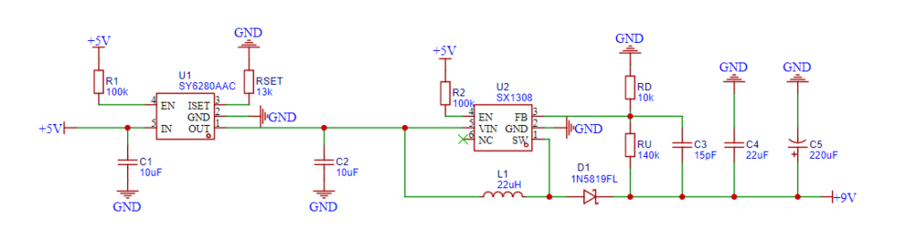
Schematic Diagram Example
Here’s an example of power supply schematic diagram.

Schematic Diagram Symbols
There are many types of schematic diagram symbols, such as power source, resistors, capacitors, inductor and coil, switch and contact, semiconductor diode, transistor, etc.
Resistor Symbol 
| Name | Abbreviation | IEC (International) | ANSI (US) |
|---|---|---|---|
| fixed resistor | R |  |  |
| varistors / rheostat |  |  | |
| potentiometer |  |  | |
| preset resistor |  |
Capacitor Symbol
| Name | Symbol | Description |
|---|---|---|
| non-polarized capacitor |  | can be connected in either direction |
| polarized capacitor |  | have a specific positive and negative lead |
| variable capacitor |  | can change the distance between the metal plates inside the capacitor |
Schematic Diagram Tool
A schematic diagram tool is a software application that allows users to create diagrams to represent systems or processes using symbols and lines. These tools are commonly used in engineering, electronics, and other technical fields to create visual representations of complex systems. Examples of schematic diagram tools include:
- AutoCAD Electrical
- Visio
- Altium Designer
- Eagle PCB Design Software
- CircuitMaker
Schematic diagram tools typically include a library of symbols and components that users can drag and drop onto the canvas to create their diagram. Users can also add annotations, labels, and text to provide additional context and explanation for the diagram. These tools often support collaboration features, allowing multiple users to work on the same diagram simultaneously. Schematic diagram tools can save time and improve accuracy compared to creating diagrams manually by hand. They can also generate reports and documentation automatically, making it easier to share and communicate the design with others. Schematic diagram tools can also help identify errors and potential issues before a system is built, saving time and resources in the long run.
Schematic Diagram vs Wiring Diagram
Schematic diagrams and wiring diagrams are two types of diagrams that are commonly used in electrical engineering and related fields. Although they serve a similar purpose, they have some fundamental differences in terms of their structure and use.
Schematic Diagram
A schematic diagram is a type of diagram that illustrates the electrical connections and functions of a circuit or system. It typically uses symbols and abbreviations to represent the various components and their relationships. Schematic diagrams are often used to design, analyze, and troubleshoot electronic circuits and systems. They help engineers and technicians to understand the overall structure of a system and how it operates.

Wiring Diagram
On the other hand, a wiring diagram is a type of diagram that illustrates the physical layout of wires and connections in a circuit or system. It shows the actual wiring between components and how they are connected to each other. Wiring diagrams are often used by electricians and technicians to install and repair electrical systems. They help to identify the correct wires to connect and ensure that the system operates safely and efficiently.