What is Keil μVision5?
Keil μVision5 is an embedded software development tool used for writing, debugging, and testing applications for embedded systems. It provides various features and tools, including a code editor, compiler, debugger, simulator, and performance analyzer, to support the development of hardware and software platforms. Keil μVision5 supports multiple programming languages, including C, C++, and assembly language, and is compatible with many popular embedded operating systems. It also offers practical tools such as real-time variable monitor, memory mapper, and timeline analyzer to assist developers in debugging and optimization during the development process.
Keil Related Terms
IDE
Integrated Development Environment, which means development integrated environment, generally includes tools such as code editor, compiler, debugger and graphical user interface.
Keil
Keil is a company name, and the software developed by it are all named starting with Keil. Currently there are Keil MDK-ARM, Keil C51, KeilC166 and KeilC251 versions.
uVision
uVision is an integrated development environment (IDE) developed by keil, which can perform code editing, file management, program compilation and debugging, etc. It contains four versions: uVision2, uVision3, uVision4, and uVision5. The latest version is uVision5.
MDK、C51
If you want to develop ARM core chips, you need to install MDK-ARM. If you want to develop 51 core chips, you need to install c51. In other words, MDK and c51 are just different development integrated environments developed by Keil for different chip cores.
CMSIS
ARM Cortex™ Microcontroller Software Interface Standard (CMSIS: Cortex Microcontroller Software Interface Standard) is a vendor-neutral hardware abstraction layer for the Cortex-M processor family.
How to Use Keil μVision5?
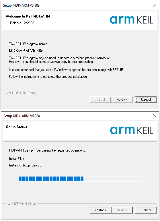
Step 1: Download and Install Keil5
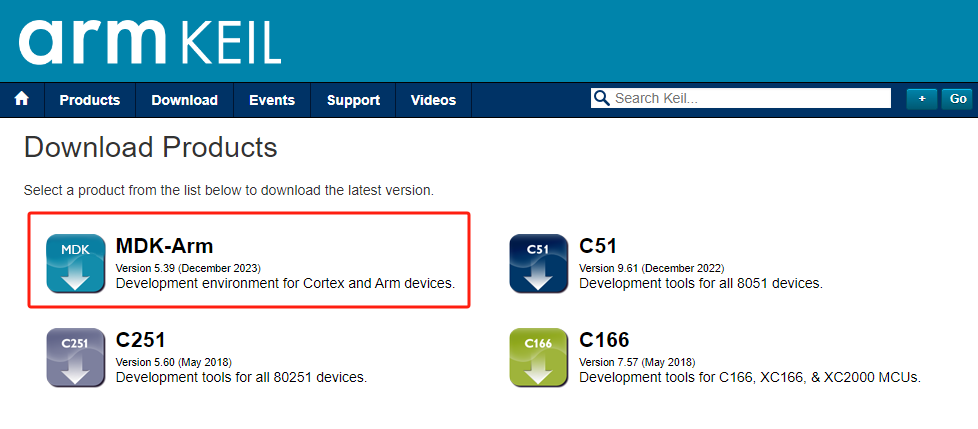
Visit the official Keil website and download the latest version of the MDK software, then proceed with the installation.
Step 2: Installing Device Packs
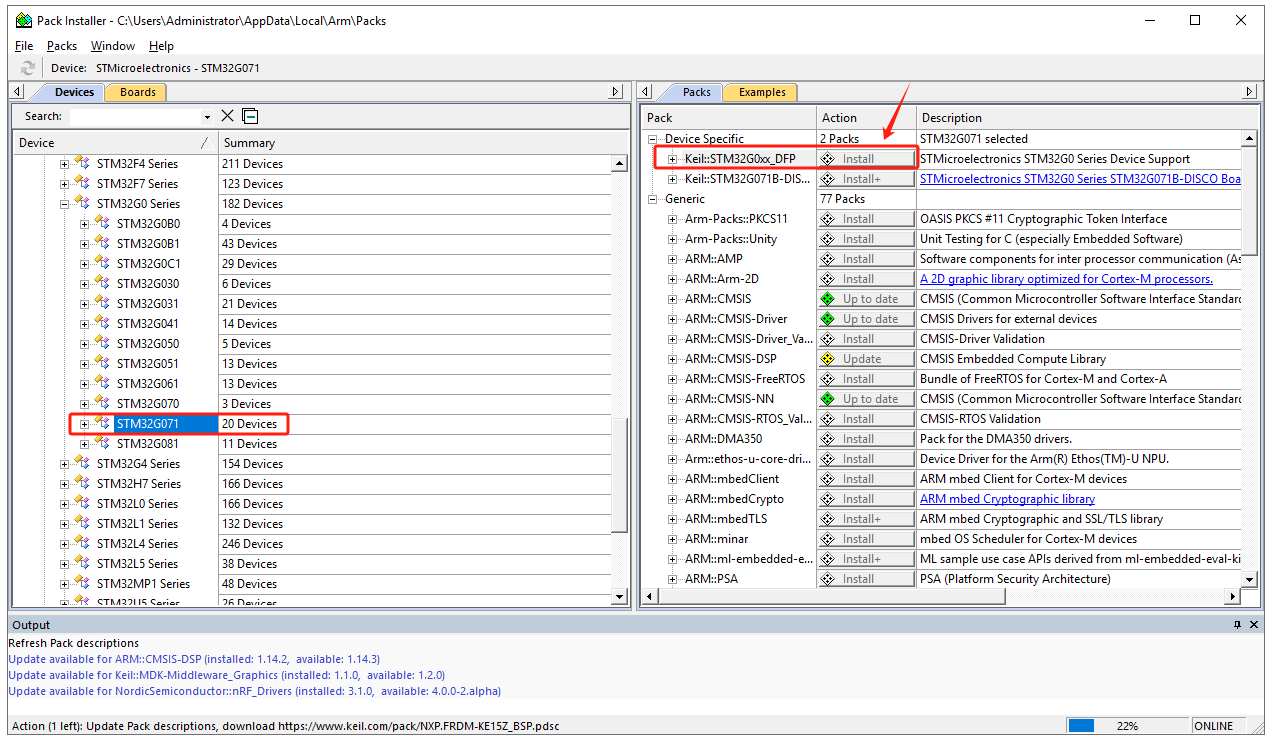
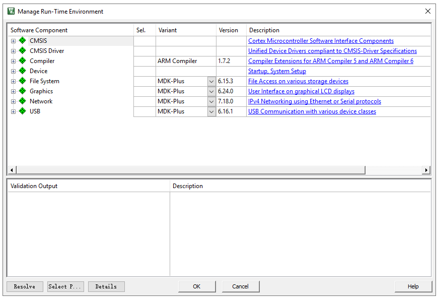
In Keil, click on “Pack Installer” to automatically update information on all device packs from the official website. After the update, select the desired chip model, e.g., STM32G071, and in the right window, find “Device Specific” -> “Keil:STM32G0xx_DFP” and click “Install” to download and install. Once completed, the “Install” button will change to “up to date,” indicating successful installation.
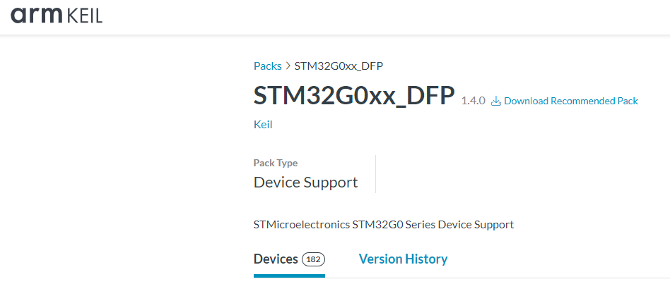
If unable to install from Keil, download the required device pack from the Keil official website:
https://www.keil.arm.com/packs/stm32g0xx_dfp-keil/devices/
Step 3: Creating a New Project
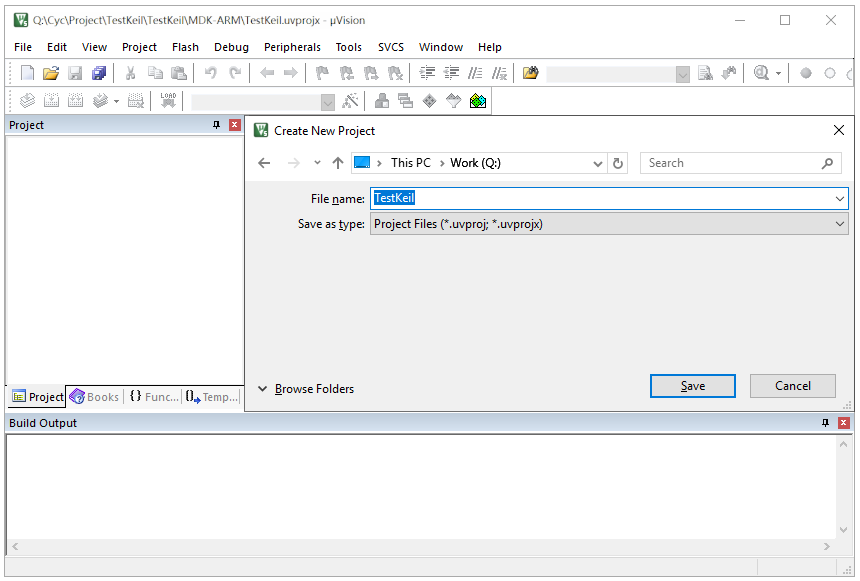
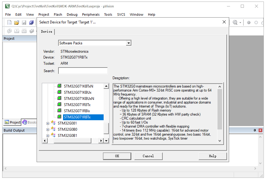
Click on “Project” -> “New Project” to create a new project. Choose the project’s save path and set the project name. The software will prompt for the MCU model; select STM32G071RBTx and choose the CMSIS interface standard.
Step 5: Project Configuration
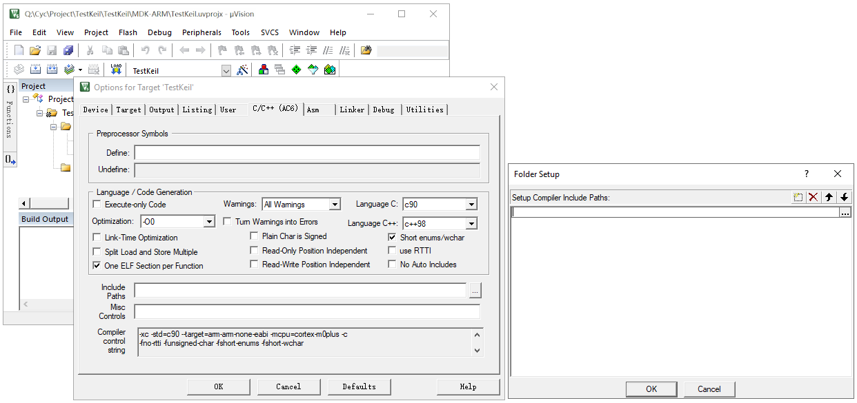
Include header file paths manually for the core code files.
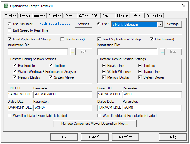
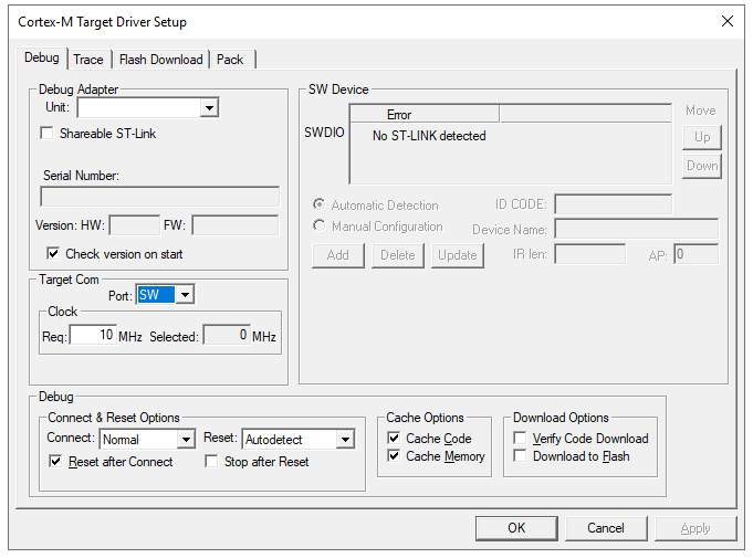
Select the debugger type, e.g., ST-Link, for online debugging.
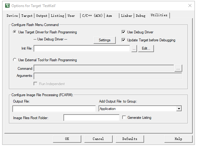
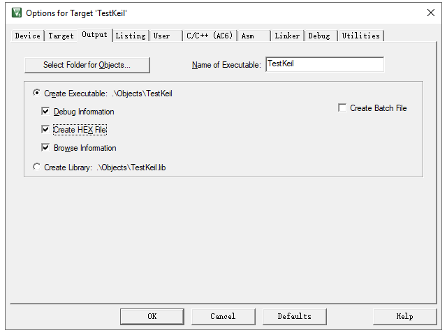
Choose “Create HEX File” to generate a Hex executable file.
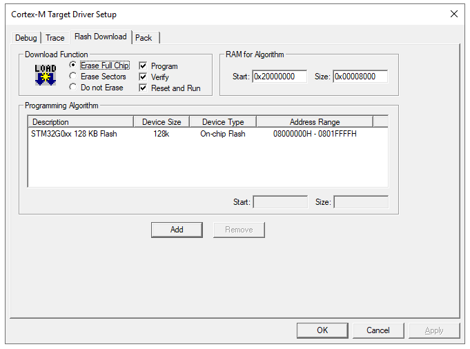
Select “Reset and Run” to run the program immediately after programming.
Step 6: Compilation
After adding files and configuring the project, click on compile. The software will invoke the compiler and linker to convert the source code (.c, .h files) into a machine-readable .axf file containing binary machine code and debugging information.
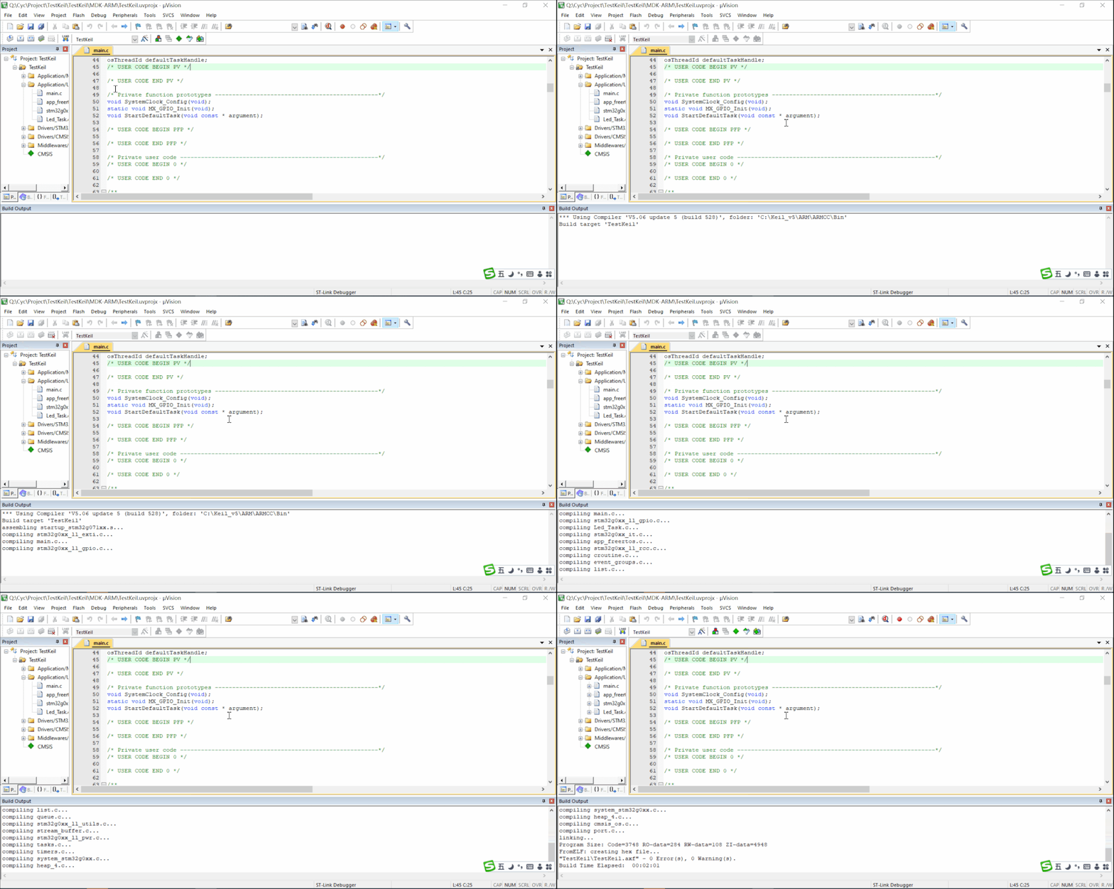
Note: Resolve any error messages before successfully generating the executable file. Warning messages can be addressed based on the situation.
Step 7: Programming
Connect the programming tool to the development board and check the connection under “Project” -> “Options for Target ‘xxx'” -> “Debug” -> “Setting.” If connected, click on “Project” to start programming. A progress bar will indicate the programming status.

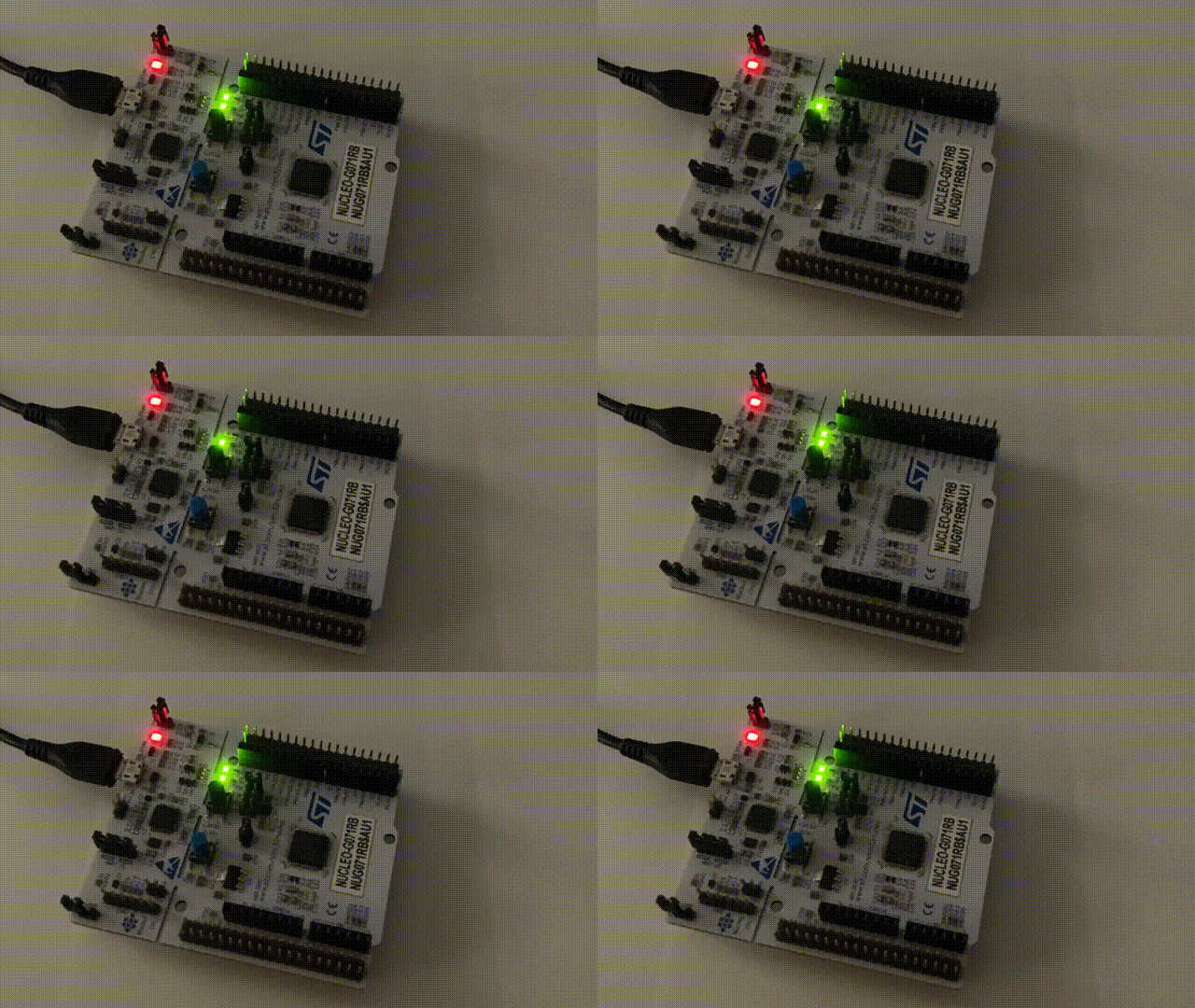
After programming, observe the board; if the LED blinks normally, the program is running correctly.
Step 8: Debugging
Online Debugging: With a development board, burn the software into the microcontroller and use the debugger to monitor the running program in real-time. Keil provides a user-friendly interface for quick issue identification.
Offline Simulation: Without a development board, use offline simulation to roughly test the logic. However, this method is not suitable if the logic involves peripherals or external circuitry.


