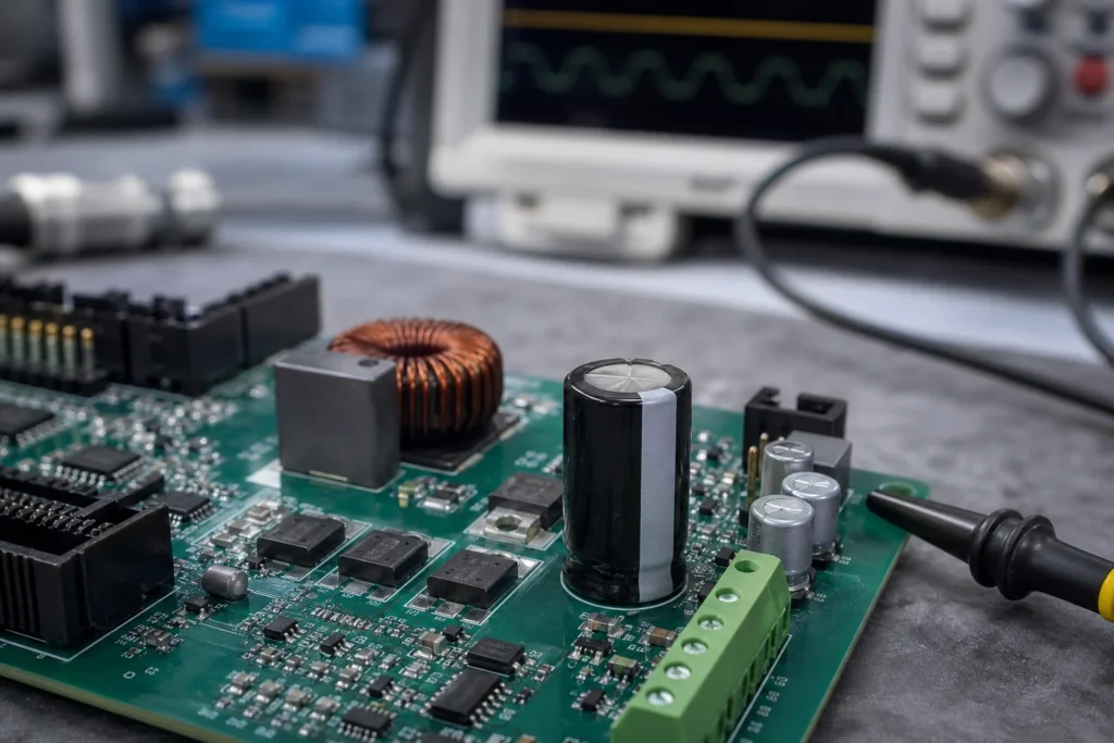
Electrolytic capacitors stay on real boards for one reason: they still deliver bulk capacitance cheaply in spaces where ripple current, startup surge, and service life matter more than miniaturization. That does not make them a default choice. On a DC input stage, LED driver, motor-control board, or legacy through-hole repair, the wrong electrolytic can dry out early, vent after thermal stress, or create avoidable rework because the package blocks inspection and test access. This guide explains how to choose an electrolytic capacitor for PCB work without reducing the decision to capacitance and voltage alone.
Where an electrolytic capacitor still makes sense on a PCB
An electrolytic capacitor earns its footprint when the circuit needs relatively high capacitance at reasonable cost, especially for input smoothing, low-frequency energy storage, hold-up support, or output filtering in power conversion stages. A 5 V logic rail may rely on MLCCs for high-frequency decoupling, but a 24 V industrial input, offline auxiliary supply, or audio power stage often still needs bulk storage that ceramics alone would make expensive, bulky in parallel count, or electrically awkward once DC bias is considered.
The useful engineering question is not ??lectrolytic or not.??It is whether the board needs bulk energy storage with predictable behavior under the actual ripple current, ambient temperature, and maintenance interval. If the board will sit beside a hot transformer, MOSFET heatsink, braking resistor, or enclosed power module, capacitor lifetime becomes a design constraint, not a purchasing detail.
The ratings that matter more than the nominal capacitance
Capacitance is only the entry point. On a practical PCB, ripple current rating, ESR, temperature rating, endurance hours, voltage derating, and physical package geometry usually decide whether the part survives the application.
Ripple current and ESR
Ripple current drives self-heating through ESR. If the capacitor sits on the input or output of a switching regulator, the part may meet the printed capacitance target and still fail early because the ripple current rating is too low for the converter waveform. This is a common failure path on dense power boards where the design review focused on value and voltage but ignored the thermal load inside the can.
Low ESR is not automatically ??etter??in every position. A controller loop tuned around a certain impedance profile may become unstable if the replacement capacitor is dramatically different from the original design. For repair work, matching the circuit function matters more than buying the part with the most aggressive marketing label.
Voltage rating and derating
An electrolytic capacitor should not be chosen at the exact steady-state rail voltage. Startup overshoot, adapter variation, regeneration events, or poor cable harness behavior can push a rail above the nominal value. A 25 V rail near long wiring or inductive loads often justifies more margin than a lab-bench prototype suggests. If the board will be exposed to automotive cranking, industrial transients, or uncertain field power bricks, voltage derating is cheap insurance.
Temperature rating and life
Lifetime on an aluminum electrolytic capacitor is strongly tied to temperature. A part rated for 2,000 hours at 105?C may last far longer in a cooler enclosure, but it will age rapidly when airflow is poor or nearby components dump heat into the same corner of the board. Layout decisions matter here: a capacitor tucked between a heatsink and a transformer can fail years earlier than the same part moved 15 mm away with better copper and air exposure.
Package choice affects assembly, inspection, and repair
An electrolytic capacitor is not just an electrical value in the BOM. Its package influences soldering behavior, board handling, AOI visibility, and field replacement risk.
Through-hole radial cans are forgiving in low-volume assembly and easier to replace in repair shops, but they consume keep-out space and can shadow nearby joints during inspection. SMD aluminum electrolytics save height and assembly steps in some products, yet they can become awkward if polarity marks are obscured by silkscreen clutter or if rework heat damages nearby plastic connectors.
Footprint orientation also matters. If the negative stripe faces away from the expected inspection side, polarity mistakes become easier during hand assembly. If the capacitor body blocks probe access to the power rail, debugging time increases later. ReversePCB readers usually see this in reverse engineering or repair work: the board is electrically simple, but one badly placed capacitor turns a straightforward measurement into partial disassembly.
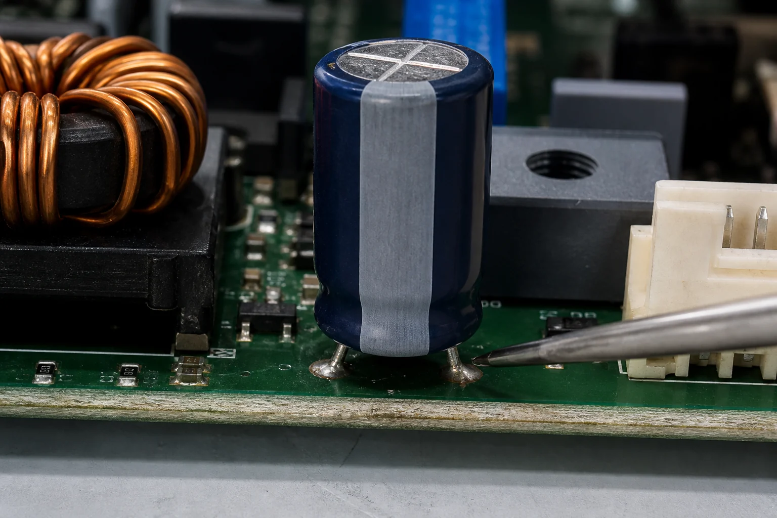
Common electrolytic capacitor failure modes on real boards
The most common failure modes are drying electrolyte, rising ESR, bulging from gas generation, leakage, polarity damage, and heat-accelerated wear. In power supplies, these faults often show up first as unstable startup, increased ripple, audible noise, dim displays, or resets under load rather than a visibly exploded part.
Inspection should go beyond ??s it bulging.??Check whether the rubber seal is pushed, whether the board shows residue near the vent or base, whether the solder joints have browned from heat, and whether the capacitor sits beside a heat source that makes repeat failure likely after a like-for-like replacement. If the design uses glue, verify that aged adhesive has not become conductive or corrosive around adjacent leads.
During troubleshooting, a capacitance reading alone can be misleading. A capacitor may measure near nominal capacitance at low test frequency yet still be unusable in circuit because ESR has drifted high. That is why a repair workflow often pairs visual inspection with ESR-aware testing and a review of the surrounding power stage.
When another capacitor technology is the better choice
An electrolytic capacitor is a poor choice when the circuit needs very low inductance at high frequency, long life under severe ripple heating, tight leakage control, or operation where reversed voltage or repeated charge-discharge abuse is likely. In those cases, polymer, film, or MLCC parts may be safer even if the unit cost rises.
For example, a microcontroller decoupling network should not rely on a lone electrolytic capacitor placed several centimeters away from the IC. A fast digital load needs low-inductance ceramic parts close to the pins. Likewise, an application with frequent hot-plug events, high pulse stress, or tight impedance targets may need a mixed capacitor strategy instead of one large aluminum can dropped into the schematic as a generic bulk part.
If you are comparing options, this capacitor impedance guide is useful for understanding why frequency, ESR, and mounting reality change the behavior you actually get on the board.
A practical selection workflow engineers can use
Start with the rail function: input bulk storage, output smoothing, hold-up, timing support, or coupling. Then check the worst-case voltage, expected ripple current, ambient temperature, board hot spots, and service-life target. After that, choose a package that fits assembly and inspection constraints rather than forcing layout to accept the first acceptable BOM line.
Before release or replacement, verify four items on the real board:
- Polarity marking remains visible after placement and cleaning.
- Package height and diameter do not interfere with shielding, enclosure walls, or probe access.
- Nearby heat sources will not push the capacitor into premature aging.
- The selected part class matches the circuit role instead of only matching capacitance and voltage.
If the schematic review is unclear, it helps to cross-check how polarized capacitors are represented in documentation. ReversePCB already covers capacitor schematic symbols and when a non-polarized capacitor is the more suitable choice.
Conclusion
An electrolytic capacitor is still a practical PCB component, but only when its thermal stress, ripple load, polarity handling, and service-life limits are acknowledged early. Good capacitor selection is less about chasing the highest capacitance and more about matching the part to the rail, the layout, and the repair reality the board will face after shipment.
Can I replace an electrolytic capacitor with a ceramic capacitor on a PCB?
Only if the circuit requirements still hold. A ceramic capacitor may improve high-frequency behavior, but it usually does not replace the bulk energy storage, ripple-current handling, or control-loop assumptions of an electrolytic capacitor by itself.
What is the most common electrolytic capacitor mistake in PCB repair?
Matching capacitance and voltage while ignoring ESR, temperature rating, ripple current, and package fit is the most common repair mistake. That shortcut often causes repeat failures even when the board powers back up initially.
How do I know if an electrolytic capacitor is failing before it bulges?
Watch for unstable startup, reset events under load, increased ripple, noise in analog or audio sections, and ESR drift during testing. Many failing capacitors still look mechanically normal until late in the failure process.
Why does capacitor placement matter if the value is correct?
Placement affects heat exposure, loop inductance, inspection access, and serviceability. A correct value placed beside a hot component or far from the current loop can shorten life or reduce the intended filtering benefit.