A finished PCBA rarely fails because one engineer forgot what a resistor or connector looks like. Problems usually start when the assembled board is treated as a generic list of parts instead of a stack of electrical, thermal, and manufacturing constraints that have to work together. That is why a useful answer to “what components are on a PCBA?” has to go beyond naming parts. It needs to explain what those parts are doing on the board and how their packages change assembly, inspection, and test risk.
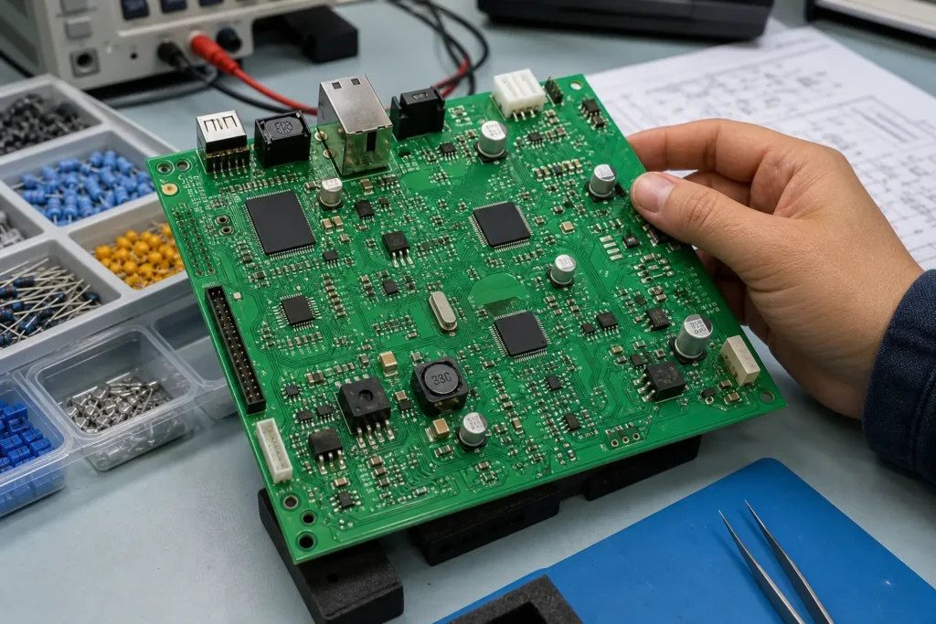
PCBA stands for printed circuit board assembly. The word matters because a PCB is only the bare board, while a PCBA is the populated, soldered, inspectable product that now has to pass power-up, test coverage, thermal limits, and field reliability. Once the board becomes an assembly, component choice stops being abstract. Package pitch, polarity, height, copper connection, and rework access all start affecting whether the job is easy to build or expensive to debug.
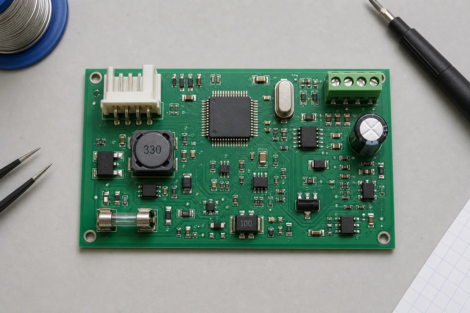
What a PCBA includes once the bare board is populated
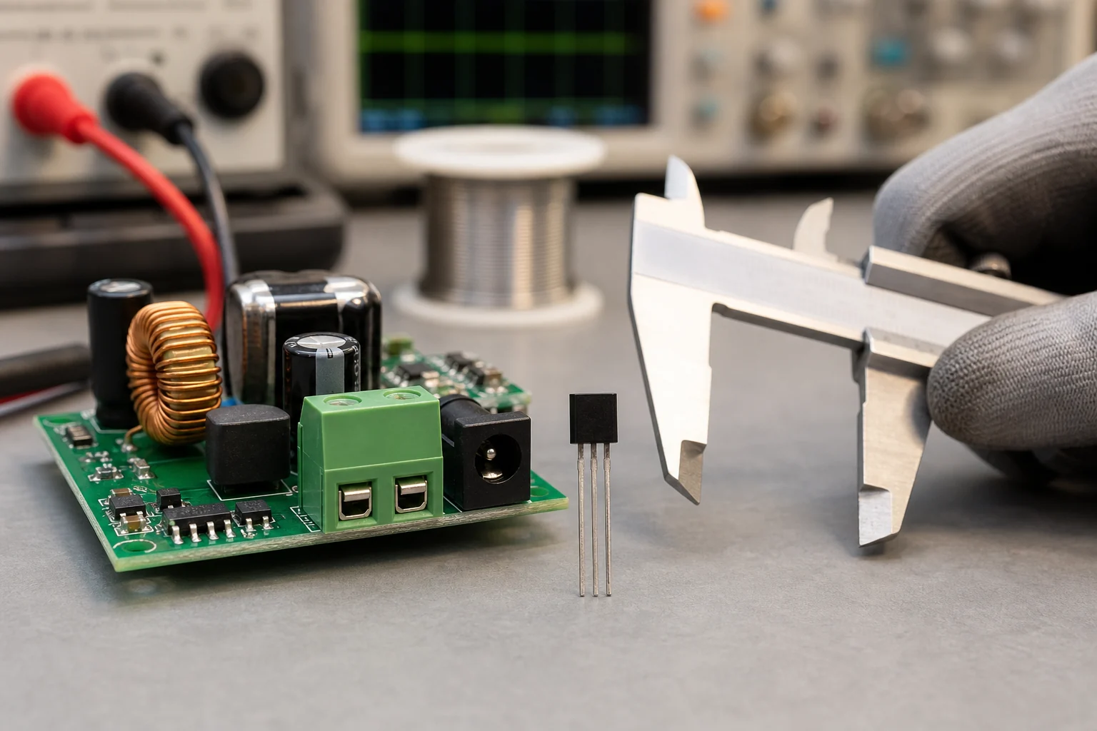
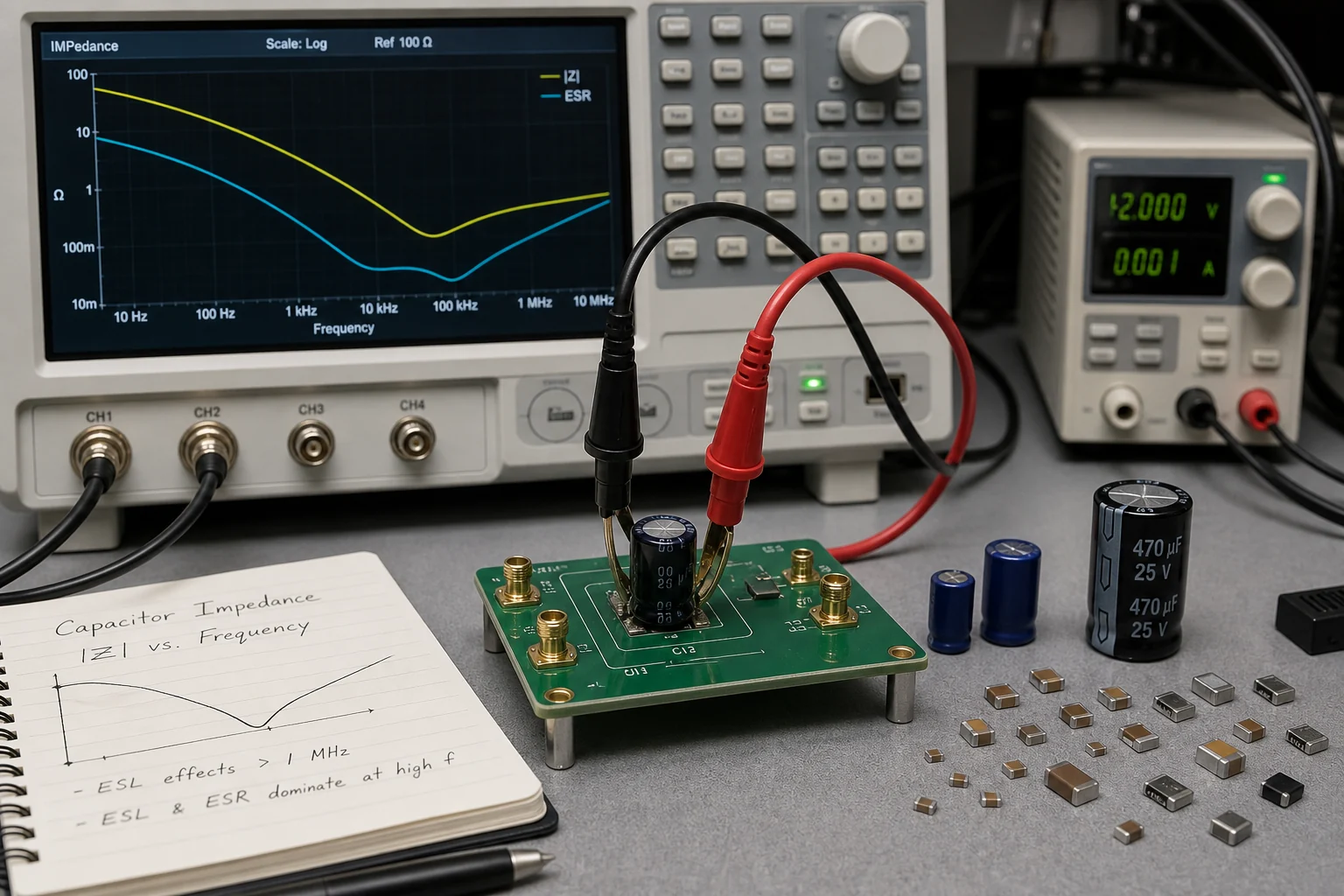
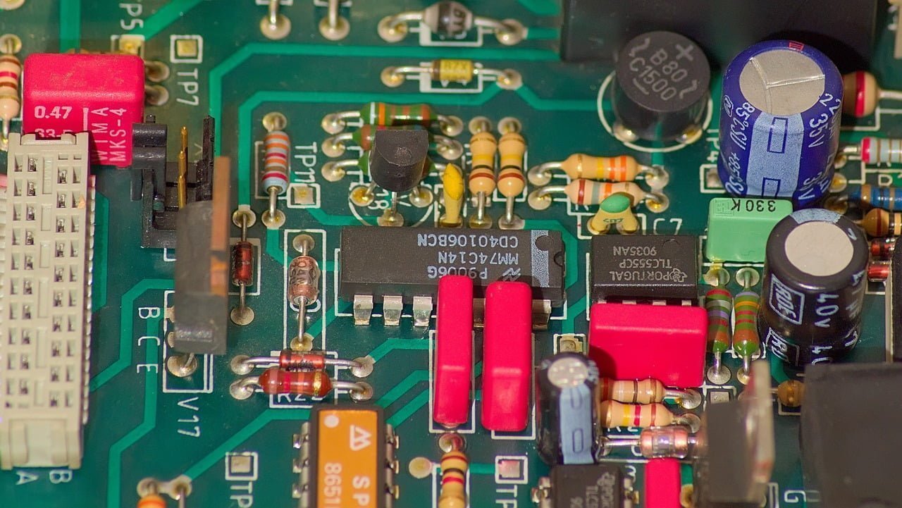
The most common PCBA component families are still familiar: resistors, capacitors, inductors, diodes, transistors, integrated circuits, oscillators, switches, connectors, and protection parts. What changes on an assembled board is the way those families interact. A ceramic capacitor may look trivial in the BOM, but if it sits beside a hot regulator and a flexing connector, solder-joint reliability becomes a layout and assembly problem. A connector may be electrically simple, but it can dominate hole quality, wave or selective solder access, and mechanical reinforcement strategy.
In most modern builds, many of those parts arrive as surface-mount packages. Small passives, QFN controllers, DFN power parts, TVS devices, LEDs, and memory packages all save space, but they also tighten stencil, placement, AOI, and rework tolerances. Through-hole parts still appear when the assembly needs mechanical strength, serviceable connectors, high-current terminals, transformers, or tall electrolytics. That mixed-technology reality is why a board that looks straightforward in schematic review can still become awkward on the line.
If you need a broader refresher on component families, ReversePCB already covers circuit board components. For PCBA work, the better question is which parts dominate manufacturing risk rather than which parts exist in theory.
The component groups engineers usually review first on a PCBA
Passive parts come first because they dominate placement count. Resistors, capacitors, ferrite beads, and inductors fill most populated boards, and their package mix affects feeder loading, tombstoning tendency, and inspection density. Fine-pitch passives near copper imbalance can skew during reflow even when the part itself is inexpensive.
Semiconductors come next because they usually control the rework budget. Microcontrollers, PMICs, FPGAs, MOSFETs, sensors, and interface ICs bring thermal pads, hidden joints, orientation constraints, and tighter profile sensitivity. The package decision for these devices is often more important than the electrical function alone. ReversePCB’s guide to surface mount device package choices is useful background when a functional part can be sourced in more than one package.
Connectors, switches, and electromechanical parts deserve separate attention because they stress the board mechanically. A USB connector, board-to-board mezzanine, or screw terminal can survive the electrical design review and still become the source of cracked joints, insufficient anchoring, warped local copper, or under-supported insertion force.
Protection and power parts are the group that often expose whether the PCBA was reviewed as a system. Fuses, TVS diodes, resettable protectors, shunts, regulators, and current-sense components must be placed where fault current, heat, and probing access still make sense after assembly. If they are hidden beside tall components or packed into thermally noisy areas, the board may pass first power-up and still fail practical service work later.
Why package mix matters more than a long component list
Two boards can contain the same logical functions and still present very different assembly difficulty. A PCBA built from 0603 passives, one QFP, and a few through-hole connectors is a different job from one packed with 0201 parts, bottom-terminated QFNs, press-fit hardware, shield cans, and mixed soldering methods. The component count may look similar, but stencil design, pick-and-place setup, profile tuning, AOI coverage, X-ray demand, and repair access are not comparable.
This is why experienced teams do not review a PCBA only as a BOM spreadsheet. They look at package density, polarity exposure, keep-out discipline, thermal asymmetry, and whether test fixtures can still reach the nets that matter. ReversePCB’s article on surface-mount layout choices shows how quickly component arrangement turns into yield, inspection, and rework consequences.
How to review common PCBA components before release
A practical PCBA review usually works better as a short sequence than as one generic DFM checkbox list.
Check package intent against the assembly process
Ask whether each critical component package matches the actual build method. A package that is easy in prototype quantities may become risky in volume if the joint is hidden, the thermal pad is large, or the nozzle and feeder combination is unstable. The assembly line must be able to place, solder, inspect, and rework the package without heroic effort.
Check polarity, orientation, and test access early
Diodes, electrolytics, LEDs, IC pin 1 marks, and keyed connectors should be obvious in both the CAD data and on the board. A board full of common components can still fail first article if visual polarity cues are weak or test pads disappear under tall parts. That is especially true on dense SMT builds where AOI can only confirm what the camera can actually see.
Check thermal and mechanical stress around the “simple” parts
Large capacitors beside hot regulators, heavy connectors at unsupported board edges, and protection parts buried next to copper pours are classic examples of ordinary components creating extraordinary failure cost. The part family is not the issue. The local board environment is.
What readers usually mean when they ask for “components on a PCBA”
Most readers are not asking for an endless catalog. They are trying to understand what turns a bare board into a working electronic assembly and which part groups deserve more attention before fabrication, procurement, and test. In that context, the useful answer is that a PCBA includes the expected electrical parts, but the engineering value comes from recognizing which ones control process risk, thermal behavior, inspection coverage, and field serviceability.
That is also why “common components on a PCBA” and “what is PCBA and its components” can be covered in one article. The search intent is the same: identify the typical part families on an assembled circuit board and understand why they matter after soldering, not just on a component poster.
Conclusion
A PCBA is more than a populated PCB. It is a board where component families, package decisions, and assembly methods now interact under real manufacturing and test constraints. Common components on a PCBA include passives, semiconductors, connectors, protection devices, and electromechanical parts, but the serious review question is how those parts affect placement, soldering, inspection, and serviceability once the board becomes a working assembly.
FAQ
What is the difference between a PCB and a PCBA?
A PCB is the bare printed circuit board. A PCBA is the assembled board after components have been mounted and soldered, so it is ready for inspection, test, and system integration.
What common components are usually found on a PCBA?
Most PCBAs include resistors, capacitors, inductors, diodes, transistors, integrated circuits, connectors, oscillators, switches, and protection parts such as fuses or TVS devices. The exact mix depends on the product function and assembly method.
Why do component packages matter on a PCBA?
Packages affect feeder setup, stencil design, solder-joint visibility, thermal behavior, inspection coverage, and rework access. Two boards with similar electrical functions can have very different assembly risk if their package mix is different.
Can a PCBA use both surface-mount and through-hole components?
Yes. Many assemblies mix SMT and through-hole parts because connectors, power hardware, transformers, or mechanically stressed parts may still be better in through-hole form while most small electrical parts stay in SMT packages.