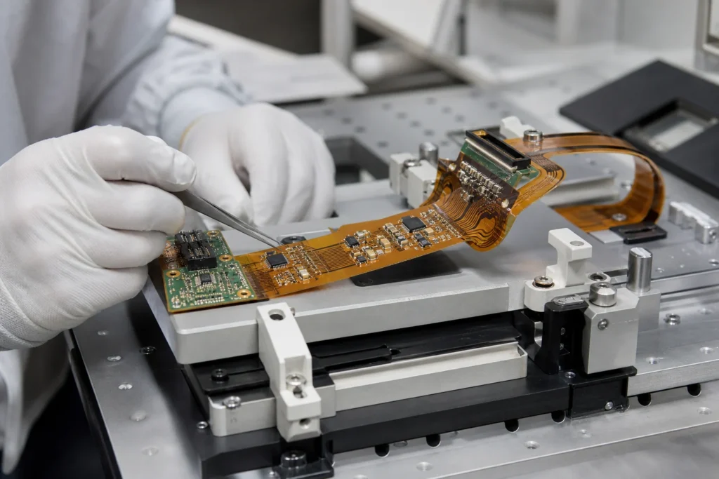
Flex PCB assembly is usually treated as a variation of ordinary SMT work until something starts cracking, lifting, or failing continuity after bend cycles. That mindset is the problem. A flex circuit is not simply a thinner rigid board. Its copper, polyimide, coverlay, stiffeners, adhesive systems, and bend zones create manufacturing risks that start long before the product reaches the field.
In many failures, reflow is not the first real mistake. The first mistake happens earlier, when a flexible circuit is unsupported during printing, distorted during placement, overhandled after soldering, or bent too close to a soldered component. By the time electrical symptoms appear, the assembly process has already reduced the life margin.
For engineers, buyers, and technicians, the practical goal is not just to “assemble” the flex board. It is to protect the structure so the product keeps working after routing, folding, vibration, and repeated use.

Why flex assembly behaves differently from rigid-board assembly
A rigid PCB carries itself through printing, placement, and reflow with relatively predictable planarity. A flex circuit does not. It can sag, stretch, curl, and shift if it is not supported correctly. That affects stencil contact, paste release, component alignment, and solder-joint geometry.
The design may also include dynamic bend areas and static fold areas. Those zones should not be treated the same way. A dynamic bend section that moves repeatedly is especially sensitive to copper work-hardening, adhesive stress, and cracks near the transition between supported and unsupported regions.
This is why flex PCB assembly is partly a mechanical-discipline problem, not only a soldering problem.
The main failure points start with handling and support
Unsupported printing
If the flex circuit is not held flat during paste printing, aperture transfer becomes inconsistent. You may see insufficient paste on some pads, smeared deposits on others, or local movement that is hard to diagnose because it changes with each panel load. A support carrier, pallet, or fixture is often the difference between a repeatable process and a line that keeps chasing false root causes.
Placement stress and local distortion
Component placement on a flex substrate works best when the board is referenced in a stable carrier. Without that support, nozzle contact, vacuum release, or feeder timing differences can slightly shift the circuit. Small motion may be tolerable on coarse parts, but not around fine-pitch packages or dense passives packed near bend transitions.
Improper bending after soldering
One of the most common practical mistakes is bending the assembly too soon or too close to a soldered area. Even if joints pass visual inspection, the local strain can damage copper traces, crack fillets, or begin separation at interfaces that only fail later in test or field service.
Stiffeners are not optional decoration
Stiffeners help control local thickness, support connectors, improve handling, and keep component zones stable. They are often the quiet reason an assembly process works. When a design leaves stiffener placement vague, the manufacturing team is forced to compensate with extra handling caution or process compromises.
The best assembly outcomes come when the stiffener strategy is tied to the real mechanical job of the product. Does the connector zone need insertion support? Does a component area need to stay flat through printing and placement? Does the bend transition need controlled distance from rigid reinforcement? Those questions belong in the manufacturing conversation early, not after yield problems appear.
Reflow still matters, but usually as a multiplier
Thermal profiling for flex circuits deserves attention because thin substrates heat quickly and can react differently from thick rigid boards. Uneven support can change heat absorption. Stiffeners and attached hardware can create local thermal mass differences. Warpage or flutter can change as the assembly heats.
Still, reflow is often a multiplier rather than the sole cause. If paste volume is unstable and board support is poor, the oven only reveals a process that was already weak. The engineering benefit comes from controlling the whole sequence: fixturing, paste deposition, placement, profile, and post-reflow handling.
How to protect bend reliability during assembly
Good flex PCB assembly treats bend zones as protected mechanical regions. Components, vias, and sharp copper features should be kept out of those regions whenever the product permits. Operators should know exactly where the no-bend and limited-bend areas are. Fixtures should support the board so natural handling does not force unintended folds.
It also helps to define when the first intentional fold is allowed. If the board is formed into shape during later integration, the assembly team should know the acceptable bend radius and sequence. Uncontrolled hand-forming on the production floor can erase the reliability margin created by good layout work.
Questions to ask a supplier about flex assembly capability
If you are choosing a manufacturing partner, ask about carriers, support tooling, bend-zone handling rules, and how they inspect flex-specific damage. A supplier may be strong in rigid-board SMT but still struggle with flex products if their process is built around self-supporting panels and rapid operator handling.
Useful questions include:
- How is the circuit supported during printing and placement?
- Where are stiffeners applied relative to component loading?
- How are bend zones identified and protected on the line?
- What handling rules exist after reflow?
- How is latent mechanical damage screened before shipment?
Those answers tell you far more than a generic claim that the shop “can do flex.”
Design and assembly teams need the same rulebook
The most successful flex builds happen when design, assembly, and mechanical integration teams agree on what must stay flat, what may bend, and when bending is allowed. That shared rulebook is essential for products that fold into housings, move with hinges, or route through tight enclosures.
If you already work with rigid-flex PCB structures, the same principle applies. The assembly process must respect the hybrid mechanical behavior of the product instead of treating everything like a rigid SMT panel.
Final takeaway
Flex PCB assembly usually fails first at support, handling, and bend-discipline, not because the concept of SMT on flex is impossible. When carriers are well designed, stiffeners are placed intentionally, bend zones are protected, and post-reflow handling is controlled, flex assemblies can be highly reliable. But when the process treats a flex circuit like an ordinary rigid board, damage starts early and often stays hidden until much later.
What is the biggest risk in flex PCB assembly?
The biggest practical risk is mechanical damage created during printing, placement, or handling, especially when bend zones are unsupported or bent too close to soldered areas.
Do flex PCB assemblies always need a support fixture?
In most real SMT processes, yes. A carrier or fixture helps keep the flex circuit flat and repeatable during paste printing and component placement.
Are stiffeners only for connectors on flex circuits?
No. Stiffeners also stabilize component areas, improve handling, and help control where strain is allowed and where the assembly must remain flat.