The keyword "relay schematic" looks broad because it is broad. Readers may be trying to decode a single relay symbol in a control board, choose a driver stage for a new PCB, or troubleshoot why a relay clicks but the load never turns on. The common problem is that many people read relay diagrams as if the coil and the contacts were two unrelated symbols. In practice, a relay schematic only makes sense when those pieces are understood together.

A relay is an electromechanical translation stage between one circuit and another. The control side energizes a coil. The switched side opens or closes contacts that route power or signals somewhere else. The schematic has to show both stories clearly: what makes the relay actuate, and what the contacts do when it actuates. That is the foundation of a useful relay article and the reason this topic still deserves its own dedicated piece even though ReversePCB already has more specific posts such as Reading a G3MB-202P Solid-State Relay Schematic Before You Switch AC Loads.
Start by separating the control path from the load path
The fastest way to understand a relay schematic is to split it into two paths. First, trace the coil circuit. What voltage powers it, what transistor or switch drives it, and what signal tells that driver to turn on? Second, trace the contacts. Are they normally open, normally closed, or changeover contacts? What load voltage and current are they switching? When those two paths are mentally separated, the relay stops looking mysterious.
This matters because failure modes live on both sides. A relay may refuse to actuate because the coil never sees full voltage. But it can also actuate correctly while the contacts are wired to the wrong terminal or damaged by load arcing. The symbol alone does not tell you which side failed. The schematic tells you where to measure next.
Coil symbols are only the beginning
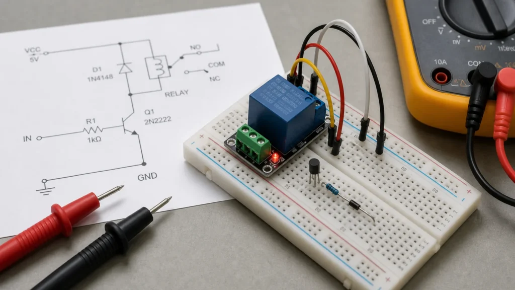
The coil is usually shown as a winding or rectangular symbol and may be labeled with a designator such as K1 or RL1. Nearby parts often matter just as much as the coil itself. A transistor, MOSFET, driver IC, optocoupler, pull-down resistor, or current-limiting element may all be part of the actuation path. If the relay is driven by a microcontroller, the schematic should also show whether the logic domain and coil supply share the same rail.
One of the most important nearby parts is the suppression element. In DC-driven relays, that is often a flyback diode. When the coil current stops, the collapsing magnetic field generates a voltage spike. Without suppression, that spike can stress the transistor, inject noise into the board, or reset nearby logic. This is not a cosmetic best practice. It is a core electrical requirement in many driver circuits.
Reading the contacts correctly
Contact interpretation is where beginners often get lost. "Normally open" and "normally closed" are defined with the coil unpowered. That means the drawn contact state may not match what the system does in operation. A relay with changeover contacts can route one node between two destinations depending on coil state, while a simple SPST relay may only connect or disconnect a single path.
The safest method is to trace continuity with the coil de-energized first, then imagine what changes when the coil is energized. This is the same style of disciplined reading encouraged in A Practical Way to Read Electrical Schematics for Circuit Work: define the current state before predicting the dynamic state. It prevents the classic error of assuming the schematic shows the "working" state rather than the rest state.
Driver design decides whether the schematic is actually buildable
A relay schematic is incomplete if it shows only a controller pin wired directly to a coil. Real boards need enough drive current, appropriate transistor gain or MOSFET choice, a base or gate network, and a supply that can tolerate the relay's inrush and hold current. The coil voltage also has to match the selected rail. A 5 V relay on a 3.3 V system is not a mere labeling issue; it becomes a reliability fault.
PCB layout influences this more than many people expect. Keep the coil-current loop compact, place the suppression device near the coil or driver, and prevent the return current from cutting through sensitive analog or logic reference areas. If the relay switches mains or other hazardous voltages, the board also needs proper creepage and clearance. A schematic may imply isolation, but the layout still has to preserve it physically.
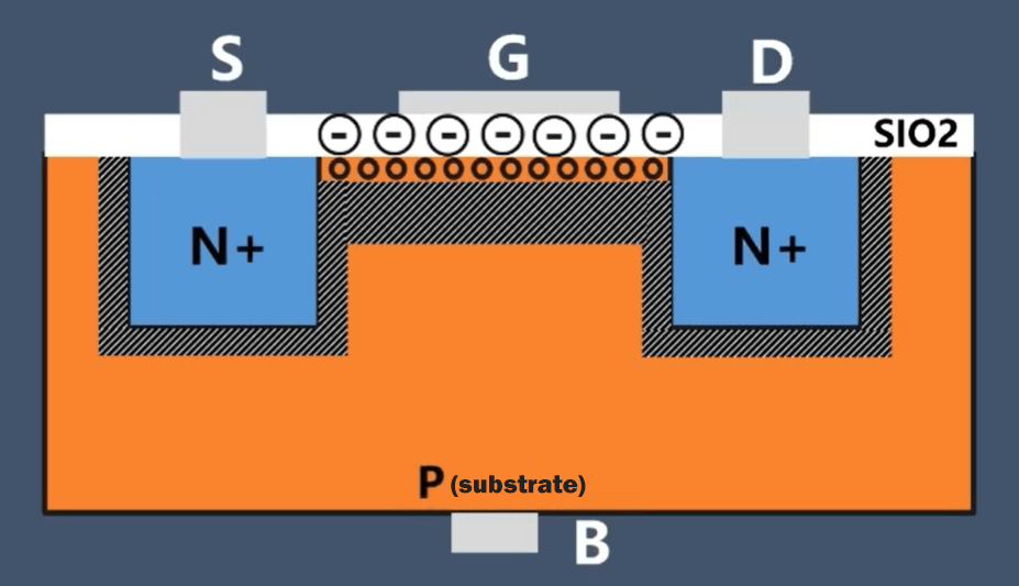
Mechanical relays are not the same as solid-state relays
Another common reading error is assuming all relay symbols point to the same behavior. A mechanical relay has contacts that move and wear. A solid-state relay usually contains an optically or electronically controlled switching element with different leakage, drop, and failure characteristics. The schematic symbol and surrounding parts reveal which family is in use. That difference matters for troubleshooting because "relay clicks but load stays off" is a mechanical-relay phrase, while a solid-state relay can fail with very different symptoms.
The broader ReversePCB article on solid-state relays is a useful internal link here because it helps readers decide whether the schematic in front of them belongs to a contact-based device or an electronic substitute. That choice affects protection, heat, EMI, and service expectations.
Practical troubleshooting order
When diagnosing a relay circuit, start at the coil supply and control signal before touching the load side. Confirm that the driver receives a valid command, the transistor saturates or switches properly, and the coil sees the intended voltage. If the relay actuates, move to the contacts and confirm continuity in the expected state. Then inspect the load path for blown fuses, damaged connectors, burned contact surfaces, or a missing neutral or return.
That order matters because relay failures are often misdiagnosed. A board may swap a perfectly healthy relay because the real problem is a dead driver transistor or a power rail collapse. On the other hand, a clicking relay does not prove the load path is healthy. Contacts can pit, weld, or carbonize. Good troubleshooting treats actuation and switching as separate verifications.
Design review checks before release
Before a relay design moves to manufacturing, review the coil voltage, driver margin, suppression method, contact rating, and load type. Inductive, resistive, lamp, and motor loads stress contacts differently. If the relay is near the edge of its rating, the schematic should not be treated as sufficient proof of safety. The board, harness, and enclosure all contribute to whether the switching path survives.
For production boards, clear labeling is also part of quality. Mark coil voltage, contact common, NO and NC terminals, isolation boundaries, and test points. Those choices make assembly and later repair far more reliable. ReversePCB's general PCB assembly guidance is relevant because a relay circuit is only as reliable as the build quality around it.
Bottom line
A relay schematic should be read as one system with two sides: the control path that energizes the coil and the load path that the contacts switch. The useful engineering questions are not only "where is the symbol?" but "what drives it, how is it protected, what changes state, and what electrical stress does the load create?" Once those questions are answered, relay schematics become far easier to design, debug, and trust.
What is the first thing to find in a relay schematic?
Start by finding the coil and then the contacts linked to it. Many mistakes happen because readers identify the switched load but never trace what actually energizes the relay.
Why is a flyback diode important in relay driver circuits?
When the coil current is interrupted, the coil generates a voltage spike. A flyback diode or another suppression method protects the transistor or controller driving the relay.
Does a relay schematic always imply isolation?
No. A relay can provide contact isolation on the load side, but the overall board may still have layout or safety issues if creepage, clearance, grounding, and routing are poor.
What causes relay circuits to fail on a PCB?
Common causes include wrong coil voltage, missing suppression, undersized transistor drive, damaged contacts, poor mains spacing, and heat or arcing on the switched load path.