The capacitor symbol looks simple until you start reading real schematics. On a beginner drawing, it may appear as two equal plates and nothing more. In a production design, a repair diagram, or a mixed analog and digital circuit, the symbol can tell you much more: whether the part is polarized, whether it is adjustable, whether it is feed-through or safety-related, and whether orientation matters during assembly and service.
That is why the search phrase “capacitor schematic symbol” deserves a practical explanation instead of a one-line definition. ReversePCB readers often move between design, layout review, assembly, and troubleshooting. In those workflows, reading the symbol correctly is not just academic. It affects component selection, footprint review, field repair, and even whether a board fails because someone installed an electrolytic capacitor backwards.

The fastest way to identify the common symbols
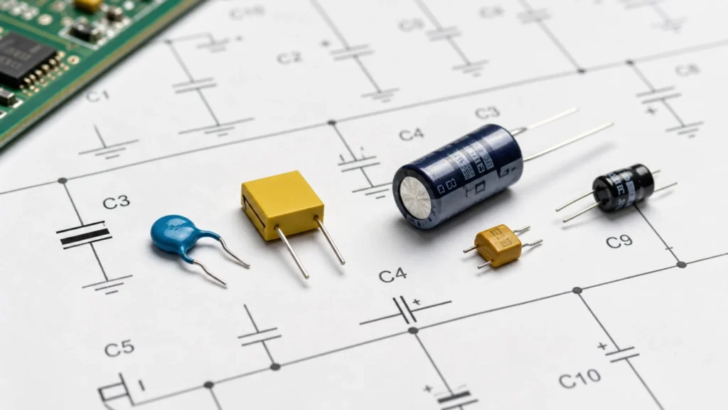
Most capacitor symbols fall into a few recognizable groups. The basic non-polarized capacitor symbol is usually drawn as two equal parallel plates. This is the symbol many engineers first learn, and it is commonly associated with ceramic, film, and other capacitors that do not require orientation by polarity.
A polarized capacitor symbol usually changes one side of the drawing or adds a polarity mark. Depending on the drafting convention, one plate may be curved, or a plus sign may appear near the positive side. That is the visual warning that orientation matters. A variable capacitor symbol usually adds an arrow that crosses the basic capacitor shape. That arrow tells you the capacitance can be adjusted. Specialty symbols, such as feed-through or filtered capacitors, may add extra structural detail because the part is doing more than simple energy storage in the line.
What the symbol is trying to tell you
A schematic symbol is shorthand for design intent. It does not show the physical package, but it often tells you what the designer expects the capacitor to do. When you see the simple equal-plate symbol next to a microcontroller power pin, the likely intent is local decoupling or high-frequency bypassing. When you see a polarized symbol near a regulator output or audio stage, the likely intent is bulk energy storage, smoothing, or coupling where orientation and voltage rating matter. When you see a variable symbol in an RF or timing section, the designer is signaling adjustability rather than a fixed nominal part.
This matters because the same capacitance value written next to two different symbols does not automatically mean the parts are interchangeable. Symbol choice and circuit context work together.
Connecting the symbol to the real component
One of the biggest beginner mistakes is assuming the symbol is just a drawing convention with no manufacturing consequence. In practice, the symbol often points to real assembly decisions. For example, a polarized capacitor symbol tells layout and assembly teams to preserve orientation from schematic to footprint to silkscreen. If that chain breaks, the board can fail immediately during power-up. A non-polarized symbol usually gives more freedom in orientation but still does not remove the need to match voltage, dielectric behavior, and package constraints.
This is why symbol literacy connects naturally to broader reading skills such as how to read PCB schematics and the more general electrical schematic diagram guide. A symbol is only one piece, but reading it well improves every later step.
Symbol variations across libraries and standards
Not every CAD library draws the symbol in exactly the same way. Different EDA tools, drafting standards, and legacy documentation styles may vary slightly in how they represent polarity, tuning, or specialty capacitor functions. That does not mean the symbol is unreliable. It means you should read it together with nearby clues: the reference designator, usually C; the written capacitance value; voltage notes; polarity markers; and the surrounding circuit function.
If a symbol looks unfamiliar, do not guess based on shape alone. Cross-check the bill of materials, part description, and placement intent. This is especially important when reviewing imported schematics, translated documentation, or older repair drawings.
Reading capacitor symbols inside real circuits
The real skill is not naming the symbol in isolation. The real skill is reading it inside a circuit. In a power supply section, small non-polarized capacitors are often there for high-frequency decoupling, while larger polarized capacitors may handle bulk smoothing. In an audio path, a polarized capacitor may serve as a coupling component where DC blocking matters. In timing or resonant networks, value stability and capacitor type become more important than just the raw symbol family.
You should also read capacitor symbols relative to nearby references such as ground, supply rails, and switching nodes. If one side connects to a noisy regulator output and the other to ground, the placement and ESR behavior may matter as much as the nominal capacitance. If the capacitor is part of a filtered I/O path, a specialty symbol may signal that the component contributes to EMC control rather than ordinary bypassing. This is one reason articles like 140 commonly used PCB markings remain useful alongside symbol-specific guides.
Common mistakes in assembly and repair
Capacitor symbol confusion causes very practical failures. The most obvious is reversed installation of a polarized capacitor. That mistake can produce overheating, leakage, swelling, or catastrophic failure. Another common mistake is replacing a non-polarized capacitor with an electrolytic part purely because the value seems to match. In repair work, that shortcut can distort circuit behavior badly.
A third mistake is ignoring the purpose of the capacitor in the circuit. A symbol near a switching regulator may represent a part chosen for ripple current and ESR behavior, not just capacitance. A symbol in an RF section may represent a variable or tightly controlled part where tolerance and physical placement are critical. For technicians and engineers doing board-level diagnostics, the best habit is to verify symbol type, circuit role, and physical part specification before replacement.
A simple checklist when you meet a capacitor symbol
When you read a capacitor symbol in a new schematic, ask whether it is polarized or non-polarized, whether it indicates a fixed, variable, or specialty capacitor, what part of the circuit it is serving, whether orientation matters in assembly or repair, and whether nearby notes confirm the intended part type. That checklist is faster and safer than jumping straight to the BOM and hoping the symbol details do not matter.
Final takeaway
The capacitor schematic symbol is simple only at first glance. In real electronics work, it communicates polarity, adjustability, and sometimes special functional intent. Reading it correctly helps you choose the right component, place it properly on the board, and troubleshoot circuits without making avoidable replacement mistakes.
For design teams, this improves schematic review and footprint validation. For assembly teams, it reduces polarity and substitution errors. For repair work, it prevents the common trap of treating every capacitor symbol as if it meant the same physical part.
What does the basic capacitor symbol with two equal plates mean?
It usually indicates a non-polarized capacitor. In many circuits that points to ceramic or film capacitors, though the exact part still depends on the value, voltage, and application.
How can I tell if a capacitor symbol is polarized?
Look for a curved plate, a plus sign, or another drafting clue that identifies polarity. Then confirm the intent with nearby values, notes, and the BOM before assembly or replacement.
What does an arrow across a capacitor symbol mean?
It normally indicates a variable capacitor, meaning the capacitance is adjustable instead of fixed.
Why is the capacitor symbol important in repair work?
Because the symbol can tell you whether orientation matters and what type of capacitor the circuit expects. Replacing a polarized or specialty capacitor with the wrong part can change circuit behavior or damage the board.