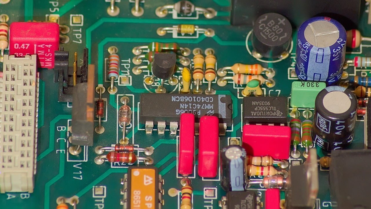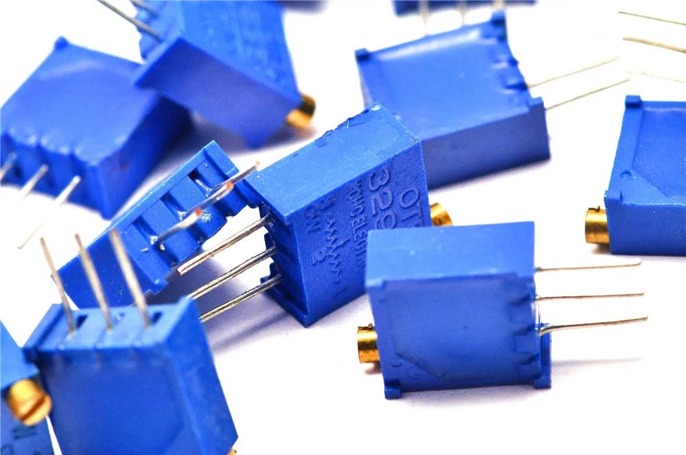
Potentiometers offer several advantages, including simple design, low cost, a wide resistance range, ease of operation, and mature technology. As reliable devices, they control, measure, and accurately sense voltage in electronic and electrical systems through linear or rotational motion. In practical applications, it’s essential to understand the technical parameters of potentiometers to select and use them correctly, ensuring the circuit operates smoothly.
What is a Potentiometer?
A potentiometer typically consists of a resistive element and a movable wiper. As the wiper moves along the resistive element, it produces a resistance value or voltage at the output that is proportional to the displacement. Potentiometers can function as three-terminal or two-terminal devices. The latter can be viewed as a variable resistor, as their role in a circuit is to obtain an output voltage related to the input voltage (applied voltage), hence the name “potentiometer.”
Potentiometer Symbol
The circuit symbol for a potentiometer is “RP“, where the “r” stands for resistor and the “p” indicates that it has an adjustment function.

Operating Principle of Potentiometer
A potentiometer is an adjustable electronic component. When a voltage is applied across the two fixed contacts of the resistive element, turning or sliding the wiper changes its position along the resistive element, resulting in a voltage that relates to the wiper’s position. It is primarily used as a voltage divider, making it a four-terminal component. Essentially, a potentiometer is a type of sliding rheostat, commonly used for volume control in speakers and power adjustments in laser devices.
How to Connect a Potentiometer?
A standard potentiometer has three terminals; the resistance between the outer terminals is fixed, while the resistance between the middle terminal and either outer terminal is variable. In other words, the potentiometer divides into two series resistors from the middle terminal, with a fixed total resistance. When used as a variable voltage divider, one outer terminal connects to the input voltage, the middle terminal connects to the output, and the other outer terminal connects to ground. As a variable resistor, one outer terminal connects to the input voltage, the middle terminal connects to the output, and the remaining terminal can be left unconnected or connected to the middle terminal.

Example of Potentiometer Use
Reading Potentiometer Values
Objective:
View the potentiometer’s input values using the serial monitor. The potentiometer acts as an analog input device, corresponding to ports A0–A5. In this experiment, I used the A0 interface.
Circuit Setup:

Code:
					int sensorValue = 0; // Potentiometer voltage value
void setup() {
    Serial.begin(9600); // Open the serial port and set baud rate
}
void loop() {
    sensorValue = analogRead(A0); // Read analog value from A0
    Serial.print("Value= ");
    Serial.println(sensorValue); // Output value to the serial monitor
    Serial.println(sensorValue, HEX); // Output value in hexadecimal to the serial monitor
    delay(100);
}
Results:
When rotating the potentiometer knob, the serial monitor displays values ranging from 0 to 1024.
Code Explanation:
(1) Serial Monitor: This tool allows us to observe data changes during experiments. For instance, in this experiment, we monitor changes in analog pin A0.
(2) Serial Monitor Commands:
- Serial.begin(baudRate): Sets the baud rate for serial data communication. The default baud rate for Arduino is 9600 bps, though other rates can be specified based on device requirements.
- Serial.print vs. Serial.println: The difference is that ln indicates a new line.
- Serial.println(b) outputs the ASCII code of b in decimal, followed by a carriage return and line feed.
Other formats include binary, octal, decimal, and hexadecimal.
(3) analogRead(): Reads analog values. In this experiment, it reads the value from analog pin A0.
Controlling LED Brightness with a Potentiometer
Objective:
Change the LED brightness by rotating the potentiometer.
Circuit Setup:

- Potentiometer: OUT connects to A0, VCC to the development board’s 5V, GND to the GND.
- LED: Positive terminal connects to digital pin 10, negative terminal connects to GND.
Code:
					int sensorValue = 0; // Potentiometer voltage value
int outputValue = 0; // Analog output (PWM) value
void setup() {
    pinMode(10, OUTPUT);
    Serial.begin(9600); // Initialize serial port at 9600 baud
}
void loop() {
    sensorValue = analogRead(A0); // Read analog value
    outputValue = map(sensorValue, 0, 1023, 0, 255); // Map value range
    analogWrite(9, outputValue); // Output PWM value to control LED brightness
    Serial.print("sensor = ");
    Serial.print(sensorValue);
    Serial.print("\t output = ");
    Serial.println(outputValue);
    delay(10);
}
Code Explanation:
(1) map Function: This function proportionally transforms a variable from one range to another. For example, to convert potentiometer resistance values (0-1023) to PWM signal outputs (0-255), we can use this function effectively.
(2) analogRead(): Reads the analog value from the connected interface.
Applications of Potentiometers
Potentiometers are mainly used in two forms within electronic technology: to adjust current and to adjust voltage.
As a Current Controller: Used in generators to produce AC power, then transformed from low to high voltage and delivered to transformers for distribution to consumers.

As a Voltage Divider: Used similarly to adjust load voltage.

Cautions When Using Potentiometers
Choose different types of potentiometers based on usage scenarios. For high-power circuits, use power-type wire-wound potentiometers; for power circuits needing precise voltage adjustments, use trimmer potentiometers. It’s vital to select materials, structures, types, specifications, and adjustment methods according to specific circuit requirements.
- During installation, do not over-tighten the fixed nut, as excessive strength can prevent the potentiometer shaft from rotating.
- Avoid moisture, condensation, and debris on the potentiometer’s surface to prevent internal damage.
- Avoid unnecessary adjustments to the potentiometer when not in use, as each rotation can wear the internal shaft, eventually leading to failure.