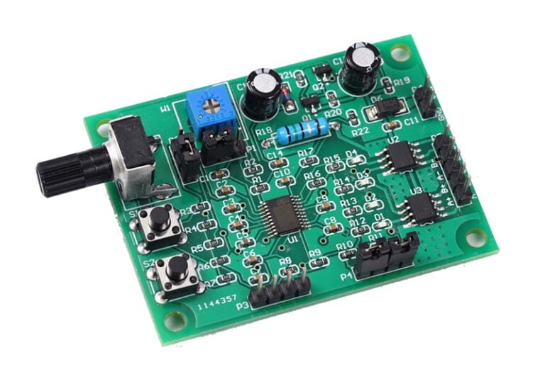
There are various drive ICs available for micro stepper motors, such as DIO5833, HR8833, SGM42633, drv8833, and more. In this article, we will introduce the principles and usage of these chips.
Schematic Diagram
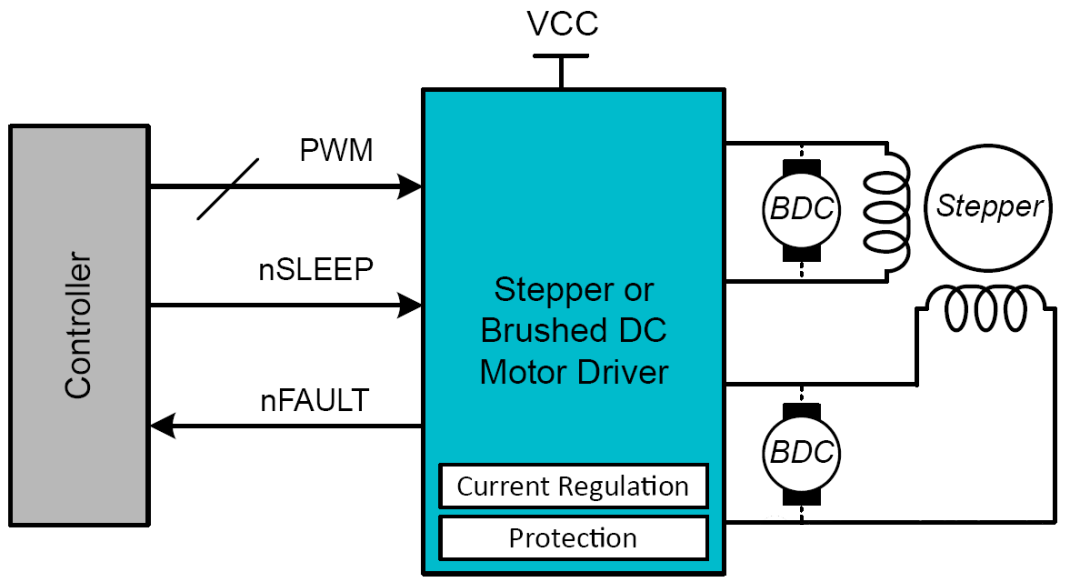
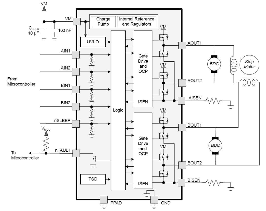
These chips are all dual H-bridge motor control ICs, capable of driving two DC motors or one stepper motor, as shown in the diagram below:
Block Diagram
As block diagram below, it’s evident that there are two H-bridges, with each H-bridge corresponding to a driver circuit and overcurrent protection circuit. Additionally, they integrate an internal pump voltage circuit for driving high-side MOSFETs. These two H-bridges can be paralleled to drive high-current DC motors. These chips incorporate various protection features to safeguard the system in case of faults, including undervoltage lockout (UVLO), overcurrent protection (OCP), and thermal shutdown (TSD).
H-Bridge Control
The table below lists the output behavior of the H-bridge under different input logics.

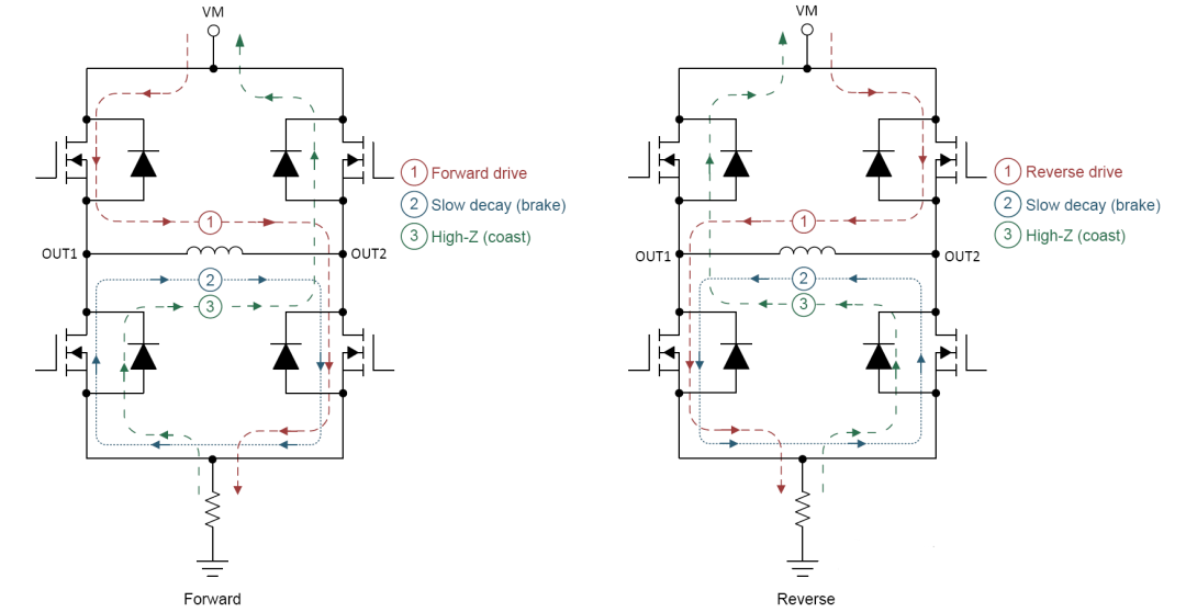
By considering the current paths outlined below, it becomes clear how changing the coil current direction achieves forward and reverse motion. Fast decay/slow decay is used to address the freewheeling issue of inductive coils when the drive stops. Fast decay allows current decay through the body diode of the MOSFET, resulting in a rapid current drop, while slow decay uses both MOSFETs in a low-side conduction mode, reducing the loop resistance and causing a slower current decrease. Fast decay provides rapid current decay with slow speed changes, akin to “coasting,” while slow decay offers slow current decay with quick speed changes, akin to “braking.”
Current Adjustment
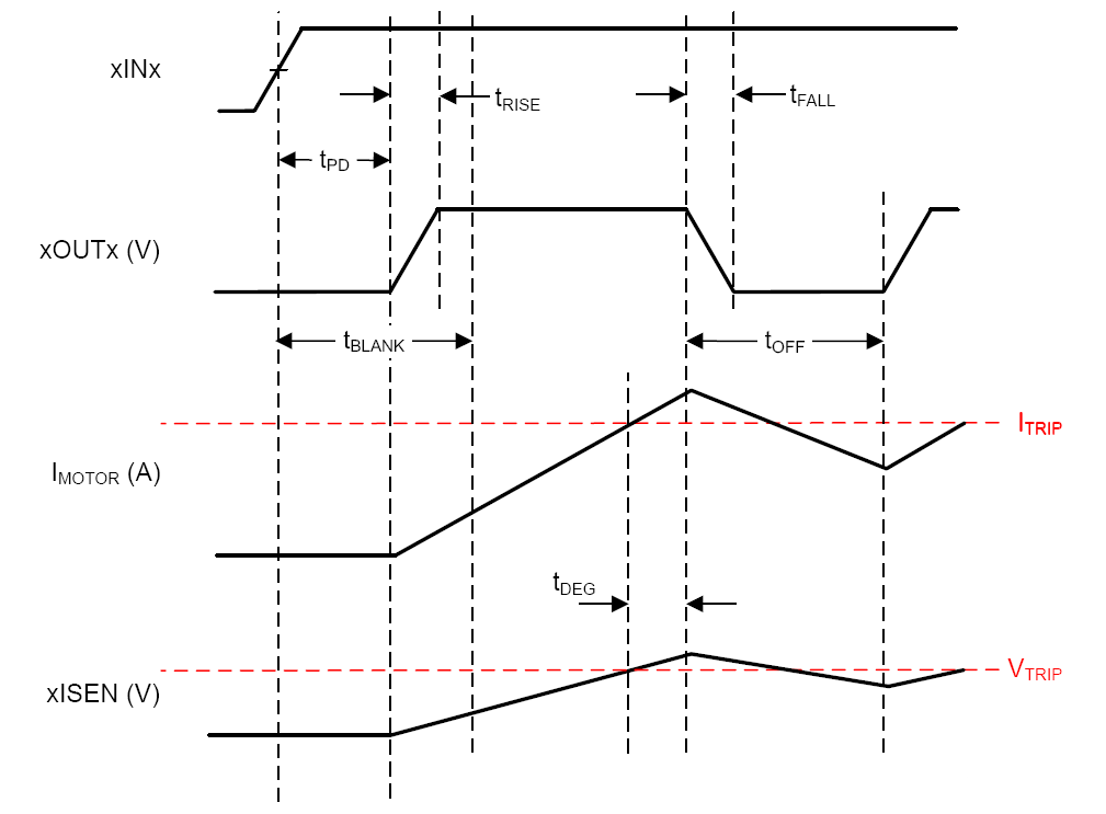
Each H-bridge has a current sensing resistor, and when the voltage drop across the resistor reaches 200mV (i.e., xISEN pin voltage VTRIP), the internal comparator inverts its output, turning off the output. After a period, when the xISEN pin voltage drops below VTRIP and the input status remains unchanged, the output is enabled again. This cycle repeats, restricting the current in the coil (winding) to a fixed value. Adjusting the current is as simple as configuring the xISEN resistor. For DC motors, this is primarily to limit start-up and stall currents (too slow or too fast). For stepper motors, it’s used after each pulse excitation due to the inherent nature of stepper motors. Therefore, for stepper motors, this resistor can be adjusted to control the current, with a higher current producing a stronger magnetic field, limited by the maximum coil current.
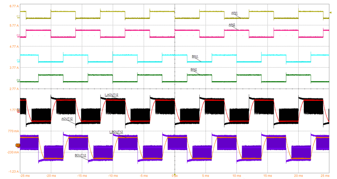
For stepper motors, the drive output always resembles a waveform similar to PWM to maintain the output current below the set value, as shown in the diagram below:
Overcurrent Protection (OCP)
Overcurrent protection refers to the circuit detecting an overcurrent condition in the H-bridge, shutting it down for protection. Simultaneously, the nFAULT pin outputs a low signal to indicate a fault. It’s crucial to distinguish this from the current control described above. They are entirely different matters, yet often confused in some articles that incorrectly claim that when the xISEN pin voltage reaches VTRIP, the nFAULT pin changes. This is inaccurate.
Thermal Shutdown (TSD)
This is straightforward: when the temperature exceeds a certain threshold, the device enters this state, and nFAULT outputs a low signal. After the temperature decreases to a certain level, normal operation resumes. When designing software or hardware, it’s important to prevent this issue by altering control logic or implementing better heat dissipation methods.
Undervoltage Lockout (UVLO)
When the supply voltage VM falls below the lockout threshold, all circuits shut down, and all internal logic resets. Simultaneously, nFAULT outputs a low signal. Normal operation can resume once the voltage recovers.
Design and Layout
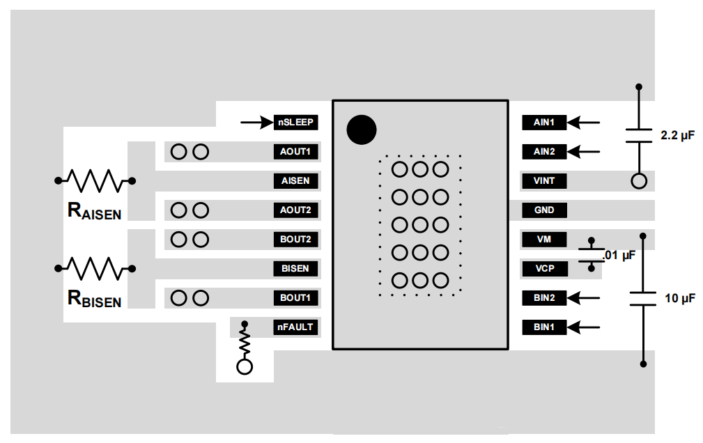
When designing the chip, place the power circuit on the left side and logic inputs on the right side for optimal performance.
