What is Logic Analyzer?
A logic analyzer is a tool that can be used to monitor, analyze, and debug digital signals. It can be used to troubleshoot problems with digital circuits, and to verify the correct operation of digital systems.
Function of Logic Analyzers
Observe the waveform
Observe whether there are glitches, interference, and whether the frequency is correct in the measurement waveform.
Timing measurement
Perform timing analysis on the measured signal to eliminate problems such as operation conflicts and timing coordination.
Auxiliary analysis
Use the logic analyzer’s comprehensive analysis capabilities to analyze bus signals or advanced protocols to accelerate development.
Troubleshoot errors
Use the powerful trigger function of the logic analyzer to capture errors, eliminate errors hidden in the system, and increase product reliability.
How does a logic analyzer work?
A logic analyzer typically consists of a central processing unit (CPU) and a number of input/output (I/O) channels. The I/O channels are connected to the device or system under test (DUT). The CPU processes the digital signals from the DUT and compare them with the set threshold voltage. In the end, they’ll be displayed on a screen or other output device.

As the picture shown above, the logic analyzer’s probe monitors data from the object, after they are connected. Then, It receives parallel data and send it to the comparator. Next, the input signal is compared with an externally set threshold level in the comparator. As a result, the comparator outputs a logic 1 if the signal is higher the threshold level. Otherwise, it outputs a logic 0.
How to use Logic Analyzers?
Now we use DSLogic’s DSView V1.2.1 x64 as a use guide for Logic Analyzer:
1. Hardware Connection
1.1 Connect DSLogic to PC
In order to achieve the best data transfer performance, please use the original or short and good quality USB cable, connect to the native port of the motherboard, and try to avoid using ports of extended hub.

1.2 Open DSView software
check the LED indicator become green, and DSView show the correct device name.

2. Hardware Options
2.1 Operation Mode
The operating modes of the logic analyzer in DSView to capture signals include stream and buffer modes. In stream mode, different channel numbers have different sampling rates, while in buffer mode the sampling rate is fixed.

2.2 Threshold Voltage
The logic analyzer supports a voltage range of 0 to 5 volts. This feature makes the logic analyzer compatible with a wide range of voltage standards. (old DSLogic hardware did not support this feature.)

2.3 Channel Mode
In Buffer Mode:
For 100MHz and below sample rate, all of 16 channels are available, for 200MHz sample rate, only 0-7 channels are available, for 400MHz sample rate, only 0-3 channels are available.
In Stream Mode:
If only 3 channels be used, the max sample rate is 100MHz. If only 6 channels be used, the max sample rate is 50MHz. If only 12 channels be used, the max sample rate is 25MHz. If all 16 channels be used, the max sample rate is 20MHz.

3. Sample Duration & Rate
3.1 Sample Duration
As figure shows, the left box indicate sample duration. There are different ranges under different mode, sample rate and channel number.

Buffer Mode: max duration = hardware depth / sample rate / channel number.
E.g, the maximum sample duration on a DSLogic Plus device using 100MB 16 channels is about 167.77 ms; on a 400MB 1 channel device, it is about 671.09 ms. If RLE compression is enabled, greater sample durations are possible, which rely on the total signal variations.
Stream Mode: max duration (64bit software) = 16G / sample rate.
E.g, the highest sample duration at 1MHz sample rate will be about 4.77 hours; at 100MHz sample rate, it will be about 2.86 minutes.
3.2 Sample Rate
There are different ranges under different mode.
Buffer Mode:
- 100M@16 channels:10KHz~100MHz
- 200M@8 channels:10KHz~200MHz
- 400M@4 channels:10KHz~400MHz
Stream Mode:
- 20M@16 channels:10KHz~20MHz
- 25M@12 channels:10KHz~25MHz
- 50M@6 channels:10KHz~50MHz
- 100M@3 channels:10KHz~100MHz
In common case, sample rate should be 4x-10x times than the highest frequency of signal be measured. For example, for a serial signal with 115200 baud rate, 1MHz sample rate is reasonable, for SPI signals with 50MHz clock, 400MHz sample rate is reasonable.
4. Trigger Setting
The figure illustrates the two trigger modes supported by DSView: simple trigger and advanced trigger. When the memory is full, fetching will pause until the memory is cleared. We can use triggers to free up extra space by configuring them to capture data. In this example, we’ll use channel 1 to capture double edges or rising or falling edges.

Notes:
Ⅰ. For simple trigger, you can use simple edge or level triggers of single or multiple channels, as well as trigger position settings.
Ⅱ. Under advanced trigger you can setup complex trigger flag, like multi-events trigger and protocol trigger.
5. Select Capture Mode
DSView support two capture modes: single capture and repetitive capture.

Single Capture:
In single capture mode, the capture operation will be resumed just once after the sample duration is reached. The capture operation will stop automatically once the sample duration is reached.
Repetitive Capture:
With this mode enabled, the capture operation will be repeated until the stop button is pressed. You can use this setting in combination with trigger settings to automatically record the waves of a specific event without having to perform extra operations. Furthermore, you can specify a repeat interval ranging from 1 second to 10 seconds.
6. Set Protocol Decoder
Click Decoder button, decoder dock will be opened. As Figure shows, decoder dock consists of two parts: decoder select, and protocol list viewer.

Select the target decoder in the combobox, click the ‘+’ button, the setting window of this decoder will be opened. For example, the figure shows the setting window of 1:UART decoder. After completion these settings, click OK to add this decoder. If data is ready, DSView will start to run the decoder and show the decoder results in wave window. More decoders can be added using the same operations.

By default, decoder will be executed from start to end for current capture. If want to decode part of the data, any cursor can be set to the start or end point.

How to choose logic analyzer?
There are several different types of logic analyzers available on the market, each with its own unique features and capabilities. Here is a list of some of the most popular logic analyzers:
Tektronix TLA7000 Series
– The Tektronix TLA7000 Series Logic Analyzer is a high-performance, modular instrument that offers a wide range of features and options. It is available in a variety of configurations, with up to 128 input channels and a choice of output options.

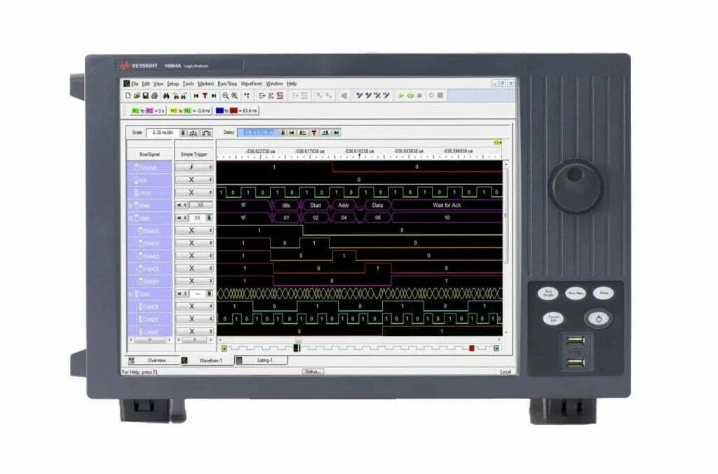
Keysight 16900A Series
– The Keysight 16900A Series Logic Analysis System is a compact, all-in-one instrument that offers a wide range of features and options. It is available in a variety of configurations, with up to 64 input channels and a choice of output options.