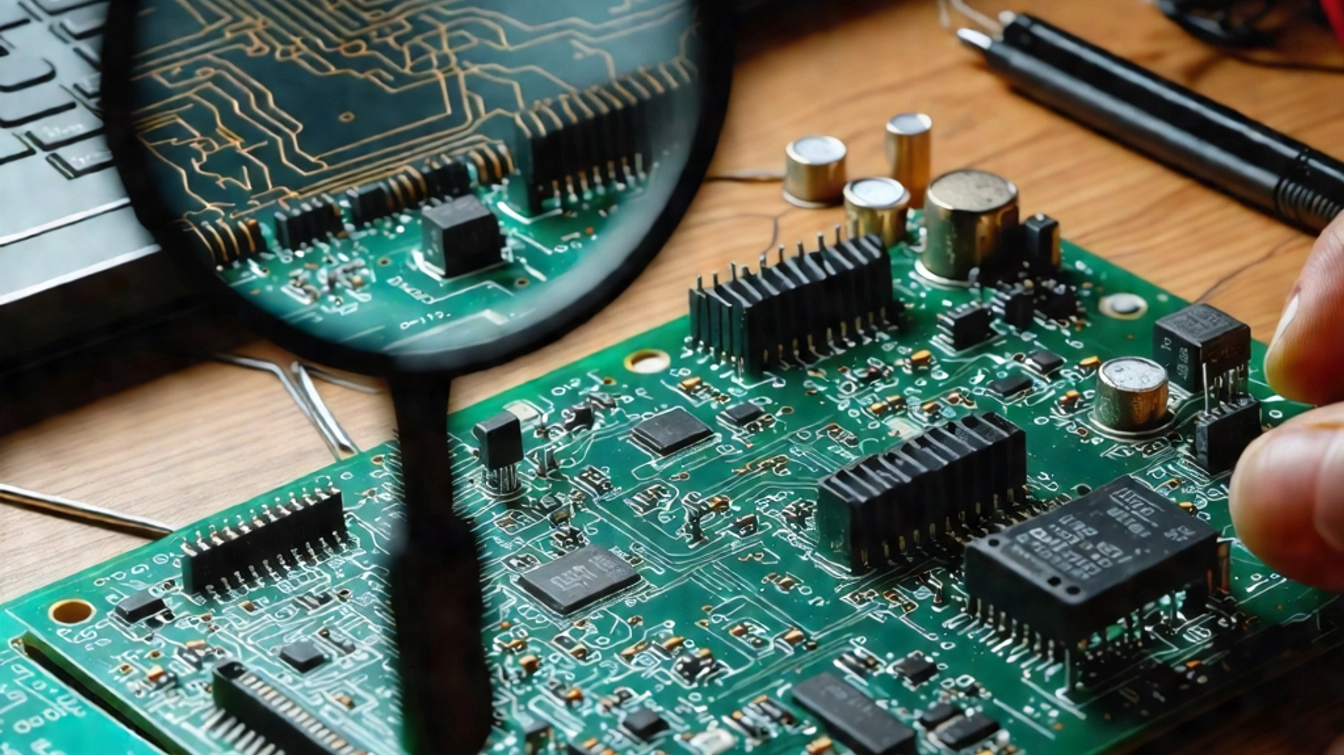
A PCB (Printed Circuit Board) schematic is the logical and visual representation of a circuit. It is the first step in the electronic product design process. In earlier times, designers would hand-draw schematics on paper. Nowadays, they utilize specialized PCB design tools, such as M-CAD and E-CAD, to streamline the design process. Following standard schematic guidelines is essential to achieve a well-structured, error-free design.
Example 1: PCB Heating Circuit Schematic
Project Overview
In this project, the circuit acts as a heating system for the PCB to maintain its temperature above the device’s minimum operational limit, particularly in low temperatures. Since precise temperature control is not required, the design uses a voltage divider composed of a resistor and an NTC thermistor to control a MOSFET or transistor. When the temperature drops below a set threshold, the voltage across the divider increases, turning on the heating circuit. As the temperature rises again, the voltage decreases, turning the circuit off.

Design Explanation
We use a common SOT-23 package for the transistor and MOSFET. MOSFETs generally support higher conduction currents compared to transistors in the same package, so we selected the LN2302BLT1G MOSFET from LRC. The NTC thermistor chosen is the commonly used NCP15WF104F03RC. For heating elements, we use a 1210-package 10Ω resistor, controlling the total power to 2.5W.
In the schematic, the signal THERM_PCB is an analog input fed to the microcontroller’s ADC for PCB temperature monitoring. The HEATER_EN signal connects to a microcontroller IO pin. The pin is set to high impedance, but if the heating circuit malfunctions, the IO can pull the signal high to force the MOSFET off as a safety measure.
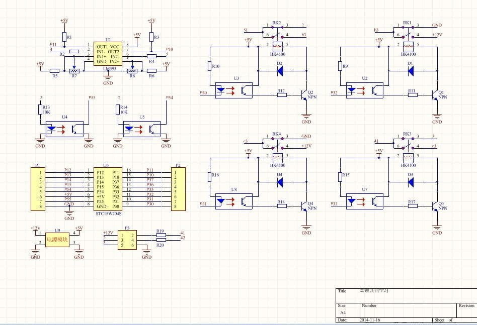
Example 2: H-Bridge Motor Driver Circuit Schematic
Project Overview
An H-Bridge motor driver manages the power and control signals for a motor, enabling bidirectional motor rotation. The L293D motor driver comes in a 16-pin PDIP package, offering internal ESD protection, high noise immunity, and a wide operating voltage range from 4.5V to 36V.

Design Explanation
The H-Bridge motor driver circuit using the L293D is simple, requiring only four external diodes. The circuit drives two motors with two input signals controlling two separate motors. Motor 1 input signals are applied to pins 1A and 2A, while outputs are from pins 1Y and 2Y. Similarly, Motor 2 input signals are applied to pins 3A and 4A, with outputs from pins 3Y and 4Y. Diodes D1–D4 protect the motors from reverse voltage spikes.
L293D Driver Component Details
The L293D is a high-current half-H driver capable of supplying up to 600mA of bidirectional drive current. It can control inductive loads, such as motors, relays, solenoids, and bipolar stepper motors.


Example 3: Switching Power Supply Circuit Schematic
Project Overview
A switching power supply, also known as a switch-mode power supply (SMPS), is a high-frequency power conversion device. Its purpose is to convert voltage from one level to another based on the needs of the end-user, using different circuit architectures.

Design Explanation
The circuit is designed to oscillate between 30kHz and 45kHz, regulated by adjusting capacitor C3 and resistor R5. The output voltage needs to remain stable, with a maximum output current of 500mA. The power supply delivers 8W of effective power with an efficiency of 87%.
Modern EDA Tools for Making Schematic
Today, designers rely on numerous EDA (Electronic Design Automation) tools like LCEDA, Altium, Allegro, Pads, KiCad, TinyCAD, and ExpressPCB. These tools help ensure that PCB schematics are error-free by continuously monitoring logic and connectivity issues. Adhering to standard design rules is crucial to make the circuit machine-readable.
Conclusion
PCB schematic design is a critical step in any electronic project. By following standard guidelines and using modern design tools, designers can create reliable and efficient circuits. The examples provided here illustrate the diversity and application of various circuit types, from simple heating circuits to motor drivers and power supplies.