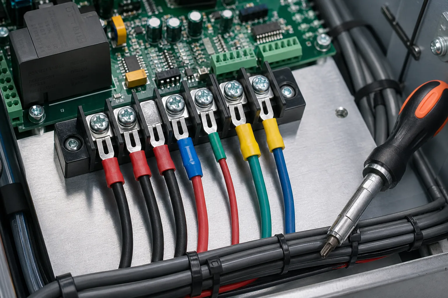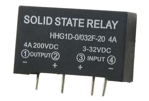
As an electrical engineer, I have always been fascinated by the complexity and intricacy of electrical systems. One component that has particularly caught my attention in recent years is the Solid State Relay (SSR). In this comprehensive guide, I will take you through the basics of solid state relays, including what they are, how they work, their advantages over traditional mechanical relays, and their various applications.
What is a Solid State Relay?
A Solid State Relay is an electronic component that is used to control the flow of electrical current without the need for any moving parts. Unlike traditional mechanical relays, which use physical contact between two conductive surfaces to complete or break an electrical circuit, SSRs use semiconductor materials such as silicon to perform the same function. SSRs are also known as semiconductor relays or solid-state switches.
How does a Solid State Relay Work?
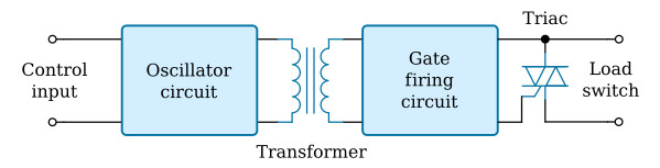
A solid-state relay consists of a sensor that is also an electronic device that responds to a control signal to turn power on or off to a load. There are different types of solid-state relays, but the main types include optically coupled solid-state relays and transformer-coupled solid-state relays. In a transformer-coupled solid-state relay, a small DC current is supplied to the primary of the transformer through a DC to AC converter.
This current is then converted to AC and stepped up to operate the solid state device (TRIAC in the following case) as well as the trigger circuit. The degree of isolation between the input and output depends on the transformer design.
In the case of optically coupled SSRs, a photosensitive semiconductor device is used to perform the switching operation. A control signal is applied to the LED, which causes the photosensitive device to enter the on mode by detecting the light emitted by the LED. Due to the photodetection principle, this type of SSR provides a relatively high degree of isolation compared to transformer-coupled SSRs.
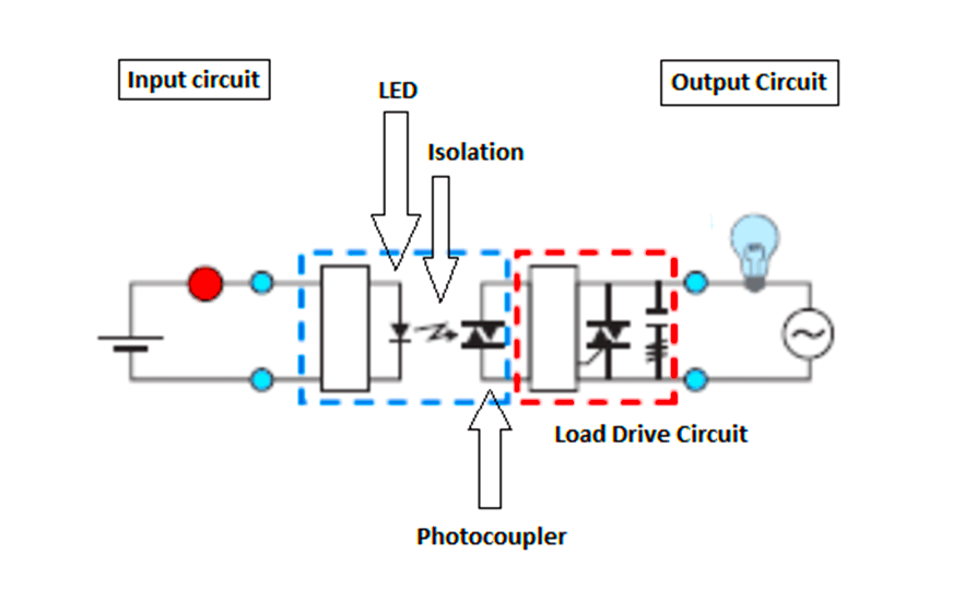
In simple works, a solid state relay is a relay without moving contacts. In terms of operation, a solid state relay is not much different from a mechanical relay with moving contacts. However, SSRs use semiconductor switching elements such as thyristors, triacs, diodes and transistors.
Solid State Relay (SSR) Structure
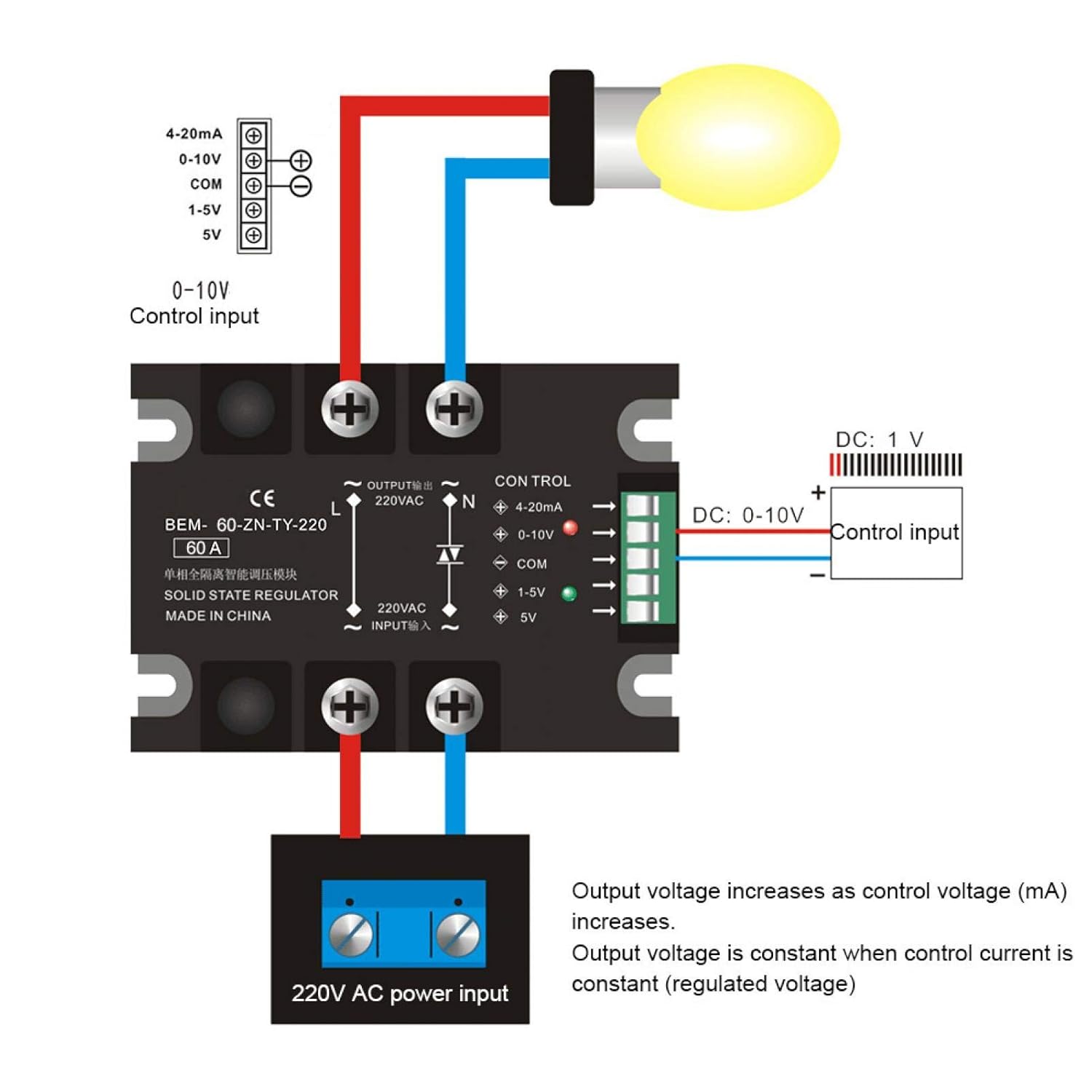
The basic structure of an SSR consists of an input circuit, an output circuit, and a control circuit.
Input Circuit
The input circuit is responsible for receiving the control signal, which is typically a low voltage DC signal. The input circuit may also include an isolation barrier that separates the control circuit from the output circuit to provide safety and prevent electrical interference.
Output Circuit
The output circuit is responsible for switching the load, which is typically an AC or DC voltage. The output circuit may consist of a triac, thyristor, or other semiconductor device. These devices are capable of handling high current and voltage levels, making them ideal for switching heavy loads.
Control Circuit
The control circuit is responsible for controlling the output circuit based on the input signal. The control circuit may include a microcontroller, logic circuit, or other control device that can detect the input signal and switch the output circuit accordingly. The control circuit may also include additional features such as overvoltage protection, thermal shutdown, or current limiting to prevent damage to the device or the load.
Applications of Solid State Relays
Solid state relays are used in a wide range of applications, including:
- Heating and cooling systems
- Lighting control
- Motor control
- Power supplies
- Industrial automation
- Medical equipment
- Security systems
Solid-State Relay Selection: Output Type, Leakage and Heat
To understand how solid state relays work, follow both sides of the isolation barrier: input current activates an isolated driver, and a semiconductor output controls the load without a mechanical armature. The output topology determines whether the relay can switch AC, DC or both and how it behaves when nominally off.
- Match the output: use zero-cross AC outputs for ordinary on/off switching, random-turn-on AC outputs for phase timing, and the specified MOSFET topology for DC or bidirectional loads.
- Check the input drive: verify control-voltage range, required current, polarity and guaranteed release level; do not assume a logic GPIO can supply the stated current.
- Account for off-state leakage: semiconductor and snubber current can illuminate LEDs or hold sensitive inputs; measure the load and add a safe bleeder only when needed.
- Calculate heat: estimate triac loss with
P≈VON×Iand MOSFET loss withP≈I²RDS(on), then apply worst-case temperature, heat-sink and enclosure limits. - Rate the real load: include motor, heater or capacitive inrush, surge, dv/dt and di/dt, plus fuse coordination, derating, isolation voltage and PCB creepage.
Conclusion
Solid-state relays are relays that use semiconductor switching elements, primarily optical semiconductors called opto-couplers, to isolate the input and output signals. The optocoupler converts the electrical signal to an optical signal and relays the signal through space, thereby completely isolating the input and output sections while relaying the signal at high speed.