In modern electronic design and reverse engineering, the 78L05 is one of the most ubiquitously used linear regulators. As a three-terminal 78L05 voltage regulator, it provides a stable +5V output in a compact footprint, making it ideal for low-power applications.
In general, voltage regulators are very common in various electronic circuits because they provide a fixed output voltage for different input voltages. The 78L05 regulator in the L78LX family uses thermal shutdown and internal current limit, making it essentially indestructible. Once adequate heatsinking is provided for this regulator (or when paired with external power transistors), it can be configured in high-current boost circuits, though its standalone rated output current is 100mA.
These types of voltage regulators are fixed in a wide range of applications. In addition, the 78L0 can also be used to build voltage regulators with large currents through power transfer elements.
About the 78L05 Voltage Regulator
In a 78L05 regulator, the first two numbers such as “78” are positive voltages, 05 is the output voltage produced by this C, such as 5V, and the letter “L” between 78 and 05 is low current, such as 0.1A. This voltage regulator is used in most electronics projects.
The output current of this 78l05 voltage regulator is rated up to 100mA, meaning the heat loss is very manageable in low-power projects. Hence, it is recommended to use a small heatsink or copper pouring on the PCB for electronic projects if it continuously operates near its maximum current limit. Another more popular voltage regulator is the 7805, but it is larger and has a high current rating of 1A. Therefore, if you are looking for a regulator in a smaller package, then the 78L05 regulator is more suitable.
Pin Configuration
The pin configuration of the 78L05 voltage regulator includes three pins, as shown in the following figure:
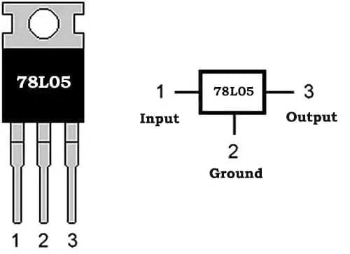
- Pin1 (Output (Vo)): This pin provides stable +5V.
- Pin2 (ground/GND): This l pin is connected to GND.
- Pin3(Input(V+)): This is a fixed input voltage.
Features
- Output Voltage Tolerance +/-5% Over Temperature
- O/P transistor safe area protection
- Thermal overload protection
- Full military temperature range
- Short circuit protection
- No additional components required
Specification
- Input voltage (maximum value) is 30V
- The output current is 100mA
- The voltage regulator positive voltage is 5V
- Working current is 5mA
- Available packages are S0-8, S0T-89 and T0-92
- With short-circuit current limiting and internal thermal overload protection
78L05 SMD Packages
When performing PCB clone or reverse engineering, identifying the 78L05 SMD variant is crucial. Unlike the classic through-hole TO-92 package, the 78L05 smd options (such as SOT-89 and SO-8) require careful thermal layout analysis:
SOT-89 Package: Often chosen for its better thermal performance in tight spaces. In reverse engineering, pay attention to the large center pad (typically connected to Ground) which acts as a heat sink on the PCB copper layer.
SO-8 Package: Widely used in multi-layer digital boards (like motherboards or sound cards). When tracing the schematic from a sample PCB, note that multiple pins might be tied to GND or NC (No Connection) depending on the specific manufacturer’s datasheet.
reverse engineering tip: Always cross-reference the top marking of the 78L05 smd component, as different manufacturers use distinct prefix/suffix codes (e.g., L78L05ACUTR, LM78L05ACM).
How to Test 78L05 Voltage Regulator?
We can test the 78L05 regulator by removing the positive probe from the i/p pin and placing it on the o/p pin, the negative probe can be placed on the GND pin. Of course, since the voltage associated with this regulator is 05, the output voltage must be 5V.
Circuit Diagram of 78L05 Voltage Regulator
The 78L05 voltage regulator application circuit is shown in the figure below. This circuit is used to regulate the 12V input voltage to 5V output voltage. In this circuit, a 78L05 voltage regulator plays a key role.
The 78L05 voltage regulator consists of three terminals namely i/p, o/p and GND. So it is very simple to use by connecting the input pin to WVi and the GND pin to system GND.
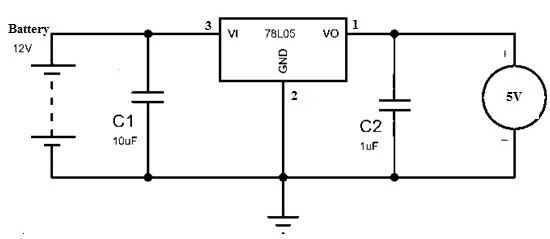
The input voltage (say 12V) is regulated to 5V with the help of a voltage regulator 1C. So this output voltage is very useful for activating small loads with a rated current well below 100mA. The maximum current supplied by the 78l05 regulator is strictly 100mA.
In the above circuit, capacitors such as C1 and C are connected to the input and output terminals. The main function of these capacitors is to filter the noise of the input voltage. Of course, it is not mandatory to use exact capacitor values, but a “C1″ value of 10u” and a “C2″ value of 1u” would be an option. Once the temperature exceeds the junction temperature, these voltage regulators can limit the current and protect the .
If you connect this circuit to a high current load, it may heat up and eventually stop working. So using a suitable voltage regulator is a perfect choice. In addition to being used as a voltage regulator, it can also be used as a short circuit protector, variable voltage regulator, current regulator, boost circuit.
Application of 78L05 Voltage Regulator
The 78L05 voltage regulator is a three-terminal fixed voltage regulator, so it is used in many applications. The 78L05 regulator features thermal shutdown and excellent internal current, which will enable its use in overload applications. Once this regulator is used to change the usual susceptibility diode, its 0/p impedance is effectively enhanced, however, the bias current is greatly reduced.
Like single-point voltage regulators that need to limit noise and solve distribution problems, the 78L05 can also be used with other power delivery devices to form a high-current regulated voltage supply, such as up to 100mA regulated output current.
The application of 78L05 voltage regulator mainly has the following points:
- Current Limiter Variable Output Voltage
- LED lighting
- Portable instrument
- Microcontroller application
- Small load can supply power below 100mA
- Different circuits such as power supplies, battery chargers, output boosters, buck
78L05 Equivalent and Alternative
Alternative 78L05 regulator models that share similar +5V output specifications include the LM7805, TS78L05, NCP78L05, and MC78L05. For retrofitting a 78l05 smd design with an adjustable or modern low-dropout (LDO) alternative, engineering choices like the LM317 (configured for 5V) or AP2114-5.0 can also be considered.
Equivalent 78L05 regulator pin-to-pin replacements are the AMS7111 and standard L78L05 series from various manufacturers.
Engineering checks for 78L05 voltage regulator pinout and circuit design
Before using 78L05 voltage regulator pinout and circuit design in a PCB, firmware, repair, or validation workflow, confirm the details that usually decide whether the design works reliably instead of only reading the headline specification.
Design and troubleshooting checklist
| Area | What to check | Why it matters |
|---|---|---|
| Pinout check | Confirm input, ground, and output orientation for TO-92, SOT-89, and supplier-specific drawings | A reversed 78L05 can place raw input voltage on a 5 V rail |
| Stability | Use datasheet-recommended input and output capacitors with suitable ESR and placement | Small linear regulators can oscillate when capacitor type or distance is wrong |
| Thermal margin | Calculate dissipation from input voltage, output current, dropout voltage, and ambient temperature | The 78L05 current rating is limited by package heat, not only by the headline specification |
These checks help connect the search intent around 78L05 pinout with practical board-level decisions, component selection, and failure analysis.
Conclusion
This post introduce the basic content related to the 78L05 voltage regulator, mainly including its pin configuration, specifications, characteristics and application circuits. Its application ranges from DVD-ROM, CD-ROM, sound card, computer motherboard, to linear voltage regulator, controller and other equipment.
Frequently Asked Questions about 78L05 Voltage Regulator
Q1: What is the maximum output current of the 78L05?
While some translated datasheets or theoretical transfer element circuits mention high currents through external power transistors, the standalone 78L05 voltage regulator IC has a maximum rated output current of 100mA (0.1A). Exceeding this limit will trigger its internal short-circuit current limiting and thermal overload protection. If your project requires up to 1A, you should look into the standard 7805 regulator instead.
Q2: How do I choose between TO-92 and 78L05 SMD packages?
The choice depends on your PCB space constraints and production methods. The TO-92 is perfect for breadboarding and prototyping. However, for automated SMT (Surface Mount Technology) assembly, the 78L05 smd (SOT-89 or SO-8) is preferred. When reverse engineering a high-density PCB, always measure the pad pitch to confirm if it’s a standard SOT-89 or a smaller customized footprint.
Q3: Can the 78L05 be replaced directly by a standard 7805?
Electrically, yes, because both output +5V. However, physically and thermally, they are completely different. The 7805 is much larger (TO-220) and rated for 1A, whereas the 78L05 is designed for low-power, space-saving circuits up to 100mA. Furthermore, note that the pin configurations between TO-92 (78L05) and TO-220 (7805) are typically different (Output/GND/Input vs. Input/GND/Output)—always double-check the pinout before soldering or designing the PCB trace.