What is a Motherboard?
The motherboard, also known as the mainboard and the system board, is one of the most basic and important components of the computer. The manufacturing quality of the motherboard determines the stability of the hardware system. The motherboard is closely related to the CPU, and every major upgrade of the CPU will inevitably lead to the replacement of the motherboard.
Each component in the computer host is connected through the motherboard, and the control of system memory, storage devices and other I/O devices during normal operation of the computer must be completed through the motherboard.
Motherboard Components
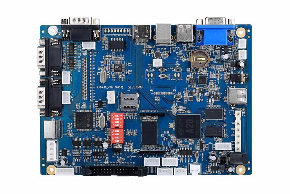
The motherboard comes with an open structure. It integrates various electronic components, sockets and interfaces, etc., providing mounting slots for CPU, memory and various function cards, such as sound cards, network cards, etc., and providing interfaces for various multimedia and communication devices.

Northbridge Chip
The chipset is the core component of the motherboard, according to the different arrangement positions on the motherboard, usually divided into northbridge chip and southbridge chip, such as Intel’s i845GE chipset is composed of 82845GE GMCH northbridge chip and ICH4 (FW82801DB) southbridge chip; The VIAKT400 chipset is composed of KT400 northbridge chip and VT8235 and other southbridge chips (there are also single-chip products, such as SIS630/730, etc.), of which the northbridge chip is the main bridge, which can generally be used with different southbridge chips to achieve different functions and performance.

Southbridge Chip
The Southbridge chip is mainly used to connect with I/O devices and ISA devices, and is responsible for managing interrupts and DMA channels to make the device work more smoothly, and it provides support for KBC (keyboard controller), RTC (real-time clock controller), USB (Universal Serial Bus), Ultra DMA/33(66) EIDE data transmission mode and ACPI (Advanced Energy Management), etc., close to the PCI slot.

CPU Slot
The CPU slot is where the processor is installed on the motherboard. The mainstream CPU slots mainly include slot370, slot 478, Socket 423 and slot A. Among them, slot370 supports PIII and new Celeron, CYRIXIII and other processors; slot 423 is used in earlier Pentium4 processors, while slot 478 is used in current mainstream Pentium4 processors. Slot A (Slot462) supports processors such as AMD’s Poison Dragon and Athlon. In addition, there are CPU slot types that support Slot7 for processors such as Pentium/Pentium MMX and K6/K6-2; SLOT1 that support PII or PIII, SLOT A used by AMD Athlon, etc.

Memory Slot
The memory slot is where memory is installed on the motherboard. At present, common memory slots are SDRAM memory, DDR memory slots, and others include early EDO and non-mainstream RDRAM memory slots. It should be noted that different memory slots have different pins, voltages, and performance functions, and different memory cannot be used interchangeably in different memory slots. For 168-line SDRAM memory and 184-line DDR SDRAM memory, the main appearance difference is that there are two notches on the SDRAM memory gold finger, while DDR SDRAM memory has only one.

PCI Slot
PCI (peripheral component interconnect) bus slot, which is a local bus introduced by Intel. It defines a 32-bit data bus and is scalable to 64 bits. It provides a connection interface for graphics cards, sound cards, network cards, TV cards, modems and other devices, and its basic operating frequency is 33MHz, and the maximum transmission rate can reach 132MB/s.

AGP Slot
The AGP Accelerated Graphics Port is an interface dedicated to 3D accelerator cards (3D graphics cards). It is directly connected to the northbridge chip of the motherboard, and the interface allows the video processor to be directly connected to the main memory of the system, avoiding the formation of system bottlenecks through the narrow bandwidth PCI bus, increasing the data transmission speed of 3D graphics, and calling the system main memory in the case of insufficient video memory, so it has a high transmission rate, which is incomparable with PCI and other buses. AGP interface can be mainly divided into AGP1X/2X/PRO/4X/8X and other types.

ATA Interface
The ATA interface is designed to connect devices such as hard disks and optical drives. The mainstream IDE interface is ATA33/66/100/133, ATA33, also known as Ultra DMA/33, which is a synchronous DMA protocol developed by Intel, the traditional IDE transmission uses one side of the data trigger signal to transmit data, and Ultra DMA uses both sides of the data trigger signal when transmitting data, so it has a transmission speed of 33MB/s.
ATA66/100/133 is developed on the basis of UltraDMA/33, and their transmission speed can reach 66MB/s, 100M and 133MB/s, respectively, but to achieve a speed of about 66MB/s, in addition to the support of the motherboard chipset, it is necessary to use an ATA66/100 dedicated 40PIN 80-line dedicated EIDE cable.

Power Slot
There are two main power slots: AT power slot and ATX power slot, and some motherboards have both slots. AT sockets have long been used and have now been phased out. The 20-port ATX power slot adopts an anti-plug and reverse design, which will not burn the motherboard because of plugging in like the AT power supply. In addition, there are generally power supply and voltage stabilization circuits of the motherboard near the power outlet.
The power supply and voltage stabilization circuit of the motherboard is also an important part of the motherboard, which is generally composed of capacitors, voltage regulator blocks or triode FETs, filter coils, voltage regulation control integrated circuit blocks and other components. In addition, there is generally a 4-port dedicated 12V power slot on the P4 motherboard.

Front Panel Connector
The front panel connector is where the motherboard uses to connect the power switch, system reset, hard disk power indicator and other cables on the chassis. Generally speaking, the ATX structure chassis has a total power switch wiring (Power SW), which is a two-core plug, which is the same as the Reset connector, short circuit when pressed, open circuit when released, press it, the total power supply of the computer is turned on, and then press it to turn off. The two-core connector of the hard drive indicator has a red wire. On the motherboard, such pins are usually marked with IDE LED or HD LED and are connected with red wires. After this line is connected, when the computer is reading and writing the hard disk, the light of the hard disk on the case will turn on. The power indicator is generally a two- or three-pin plug, using 1 or 3 digits, and the 1-wire is usually green.

On the motherboard, the pins are usually labeled PowerLED, and note that the green wire corresponds to the first pin (+) when connecting. When it is connected, as soon as the computer is turned on, the power light is always on, indicating that the power has been turned on. The reset header (Reset) should be connected to the Reset pin on the motherboard. Here’s what the Reset pins on the motherboard do: when they short-circuit, the computer restarts. The PC speaker is usually a four-pin plug, but in fact, only 1, 4 two wires, one wire is usually red, it is connected to the motherboard Speaker pin. When connecting, pay attention to the position of the red line corresponding to 1.
External Interface
The external interfaces of the ATX motherboard are unified integrated in the rear half of the motherboard. Today’s motherboards generally comply with the PC’99 specification, that is, different colors represent different interfaces, so as not to make mistakes. Generally, keyboards and mice use PS/2 round ports, but the keyboard interface is generally blue, and the mouse interface is generally green, which is convenient for distinguishing. The USB interface is flat, which can be connected to peripherals such as MODEM, optical drive, scanner and other USB interfaces. The serial port can be connected to MODEM and square mouse, etc., and the parallel port is generally connected to the printer.

BIOS and Battery
Basic input/outputsystem (bios) is an eprom or epprom integrated block that contains boot and self-test programs. In fact, it is a set of programs that are solidified on a computer rom (read-only memory) chip, providing the lowest and most direct hardware control and support for the computer. In addition, there is generally a battery assembly near the bios chip, which provides the bios with the current required for startup. Common bios chip identification rom on the motherboard bios chip is the only chip labeled on the motherboard, generally a double-row in-line package (dip), which is generally printed with the word “bios”, and there are many plcc32 package bios.

Types of Motherboard
AT: The AT motherboard, a classic and standard size in the realm of motherboards. It holds a significant place in history as the first choice for the IBM PC/A machine. Even some of the early 486 and 586 motherboards embraced the familiar AT structure layout. It’s like a seasoned veteran, paving the way for the generations to come.
Baby AT: Picture a cute, pocket-sized motherboard that brings a touch of charm to the computing world. Smaller than its AT counterpart, the Baby AT motherboard earned its name for its diminutive stature. It gained popularity as the go-to choice for the original all-in-one motherboards, making it a true pioneer in its own right.
ATX: Here comes the star of the show, the ATX motherboard. With improvements galore, it takes the AT design and elevates it to new heights. Optimized for component layout, it boasts better heat dissipation and integration. But there’s a catch—you need a special ATX chassis to unlock its full potential. It’s the cool, confident hero of the motherboard world, ready to power your dreams.
BTX: Brace yourself for an innovative leap in motherboard technology—the BTX. Building upon the solid foundation of the ATX motherboard, the BTX revolutionizes the component layout with a sleek, low-profile design. The masterminds behind this marvel understand the intricate dance of internal and external airflow within the chassis. They’ve optimized the motherboard layout, resulting in superior heat dissipation, higher efficiency, reduced noise, and hassle-free installation. BTX, Micro BTX, and Pico BTX variations offer diverse sizes and expandability options to cater to your specific needs.
All in one motherboard: Behold the jack-of-all-trades in the motherboard realm—the all-in-one motherboard. With integrated sound, display, and other essential circuits, it embodies convenience and space-saving prowess. Say goodbye to the need for plugging in additional cards; this motherboard has it all. Its high integration levels grant it a special place in the realm of original brand machines. However, maintenance and upgrades can be a tad cumbersome, a small price to pay for its remarkable capabilities.
NLX: Intel’s latest motherboard structure, the NLX, embraces the concept of flexibility like no other. Its standout feature lies in its ability to accommodate motherboard and CPU upgrades with ease and efficiency. No longer must one undergo the arduous process of updating the motherboard design for each CPU launch. In addition to its innovative qualities, some variations of NLX, such as Asus motherboards, incorporate the larger 3/4 Baby AT size motherboard structure, showcasing versatility and adaptability at its finest.
Motherboard Troubleshooting
The Motherboard BIOS is Damaged
The BIOS of the motherboard contains a large amount of important hardware data, if the BIOS is damaged, it is likely to directly cause the system to be paralyzed and unable to operate normally. Motherboard BIOS damage is mostly caused by the action of CTH virus, when the CTH virus invades the computer motherboard, the hard board data is lost, in this case for emergency repair, you can first check the integrity of the hard disk data to determine whether the BIOS fails. If there is still a DEBUG card in the computer motherboard, you can also effectively determine whether the motherboard BIOS is normal through the BIOS indicator on the surface of the DEBUG card. During the detection process, if it is found that the BOOT module of the BIOS is not damaged, but the monitor still cannot be displayed normally after booting, an alarm sound will be sounded in the PC speaker; If the BOOT module in the BIOS is damaged, and the power supply and hard disk can operate normally after power-on, and the CPU fan can also operate normally, but the motherboard still cannot boot, in this case, usually rewrite the BIOS through the programmer to troubleshoot related problems.
The Motherboard Capacitance is Damaged
Before repairing the failure of the computer motherboard, it is necessary to carefully check the motherboard capacitance to determine whether it has exploded or broken. During the operation of the motherboard, if the voltage is too high or the operating environment temperature is too high, the capacitor is easy to bubble or drain, resulting in a significant reduction in the capacity of the capacitor, and even the phenomenon of discapacitance occurs in severe cases, at this time the capacitor can no longer be filtered normally, then a large number of AC components will appear in the load current, and the memory and CPU will be affected by it to run abnormally. After the motherboard capacitance is damaged, this fault can be eliminated by replacing the capacitor.
The Motherboard Self-protection Locks
At this stage, most motherboards on the market have automatic detection and protection function, which will promote their operation, if voltage and power supply abnormalities, CPU overclocking, voltage is too high, etc., the motherboard will automatically lock and stop running. The specific manifestation of the motherboard self-protection lock is that the motherboard does not boot normally. For this symptom, the CMOS can be discharged and then powered on. You can also press and hold the RESET button while turning on the motherboard to directly unlock the motherboard.
Memory Alert Sound
A common issue is when the memory emits a continuous “beep” sound as an alarm. The main cause of this problem is poor contact between the memory module and the motherboard. It can happen if the memory module is not inserted properly, leaving a small gap when inserted into the memory slot. Another important factor is the poor craftsmanship of the gold fingers on the memory module. Over time, the gold plating on the surface may deteriorate, leading to poor contact. Additionally, if the memory slot quality is subpar, it can result in insufficient contact between the spring contacts and the gold fingers of the memory module. To address this issue, you can use a rubber eraser to clean the gold fingers of the memory module. Remove the module and reinsert it securely. If there are gaps, you can use hot glue to fill them and improve the oxidation issue. It’s important to note that while removing and inserting the memory module, make sure to disconnect the power cord of the computer to avoid accidental damage to the memory.
Abnormal Temperature Control
Taking the ASUS P3B-F motherboard as an example, it effectively monitors the CPU temperature using a 2-pin temperature control wire connected to the JTP pin next to the CPU socket. If a sudden blue screen occurs during usage and upon reboot, the monitor doesn’t display anything even though the optical drive and hard drive pass the self-test, the usual cause for this phenomenon is the disconnection of the temperature control wire on the motherboard, resulting in the motherboard entering a protective state and refusing further power commands. Nowadays, most motherboards equipped with temperature monitoring and protection devices can detect high CPU temperatures or malfunctions in the temperature control system connected to the motherboard. This directly affects the motherboard, causing it to enter automatic protection mode or issue an alarm. To resolve this issue, reconnect the temperature control wire and restart the computer. It’s important to note that if the motherboard still fails to start or issue an alarm, you should investigate the status of the motherboard’s temperature control device.
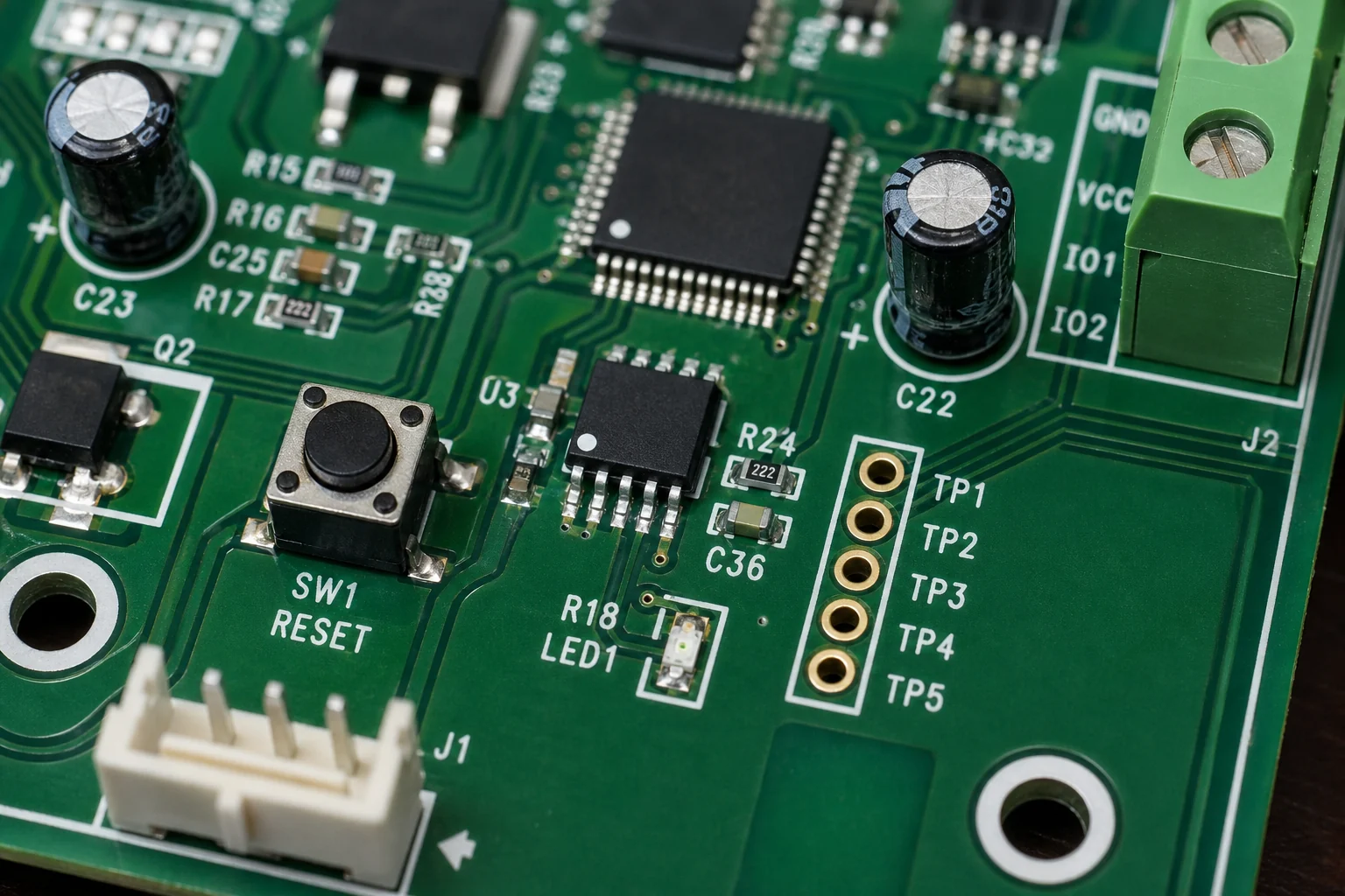
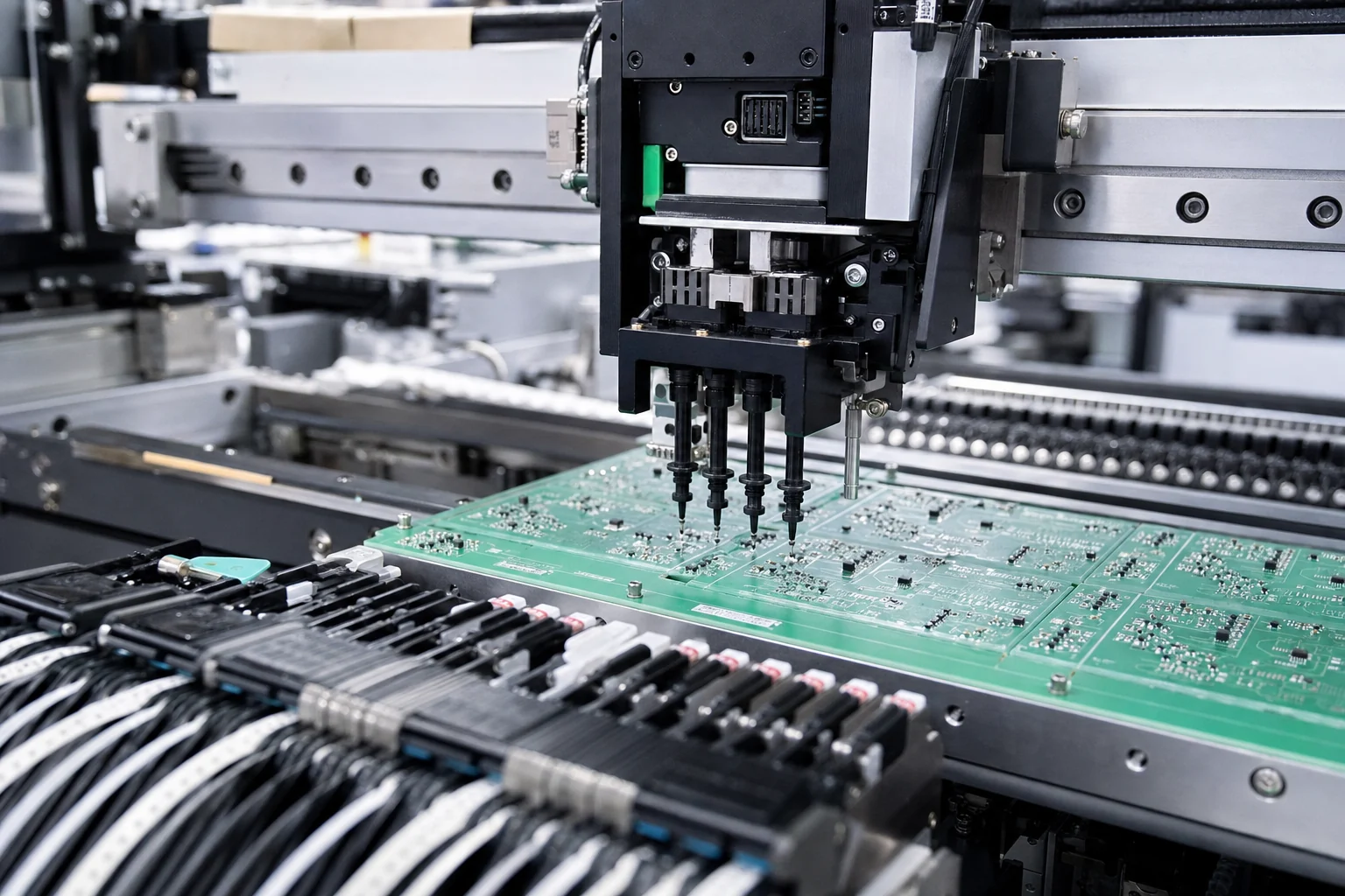
Motherboard PCB design checklist
This Motherboard PCB design checklist section helps engineers review Motherboard with focus on stack-up planning, power plane partitioning, high-speed breakout, connector keep-outs, thermal paths, and service access while keeping existing high-ranking sections unchanged.
Practical checklist
- Separate CPU, memory, and peripheral power paths early so decoupling density and return paths stay predictable across the board.
- Reserve routing corridors for DDR, PCIe, clock, and fan-control nets before placing large connectors or heat-sink hardware.
- Document debug headers, recovery jumpers, and test pads so first article bring-up does not depend on rework wiring.
Bring-up validation notes
A motherboard PCB design review should connect the layout plan with bring-up measurements, thermal checks, and debug access instead of stopping at a general motherboards explained overview.