What is QFN Package?
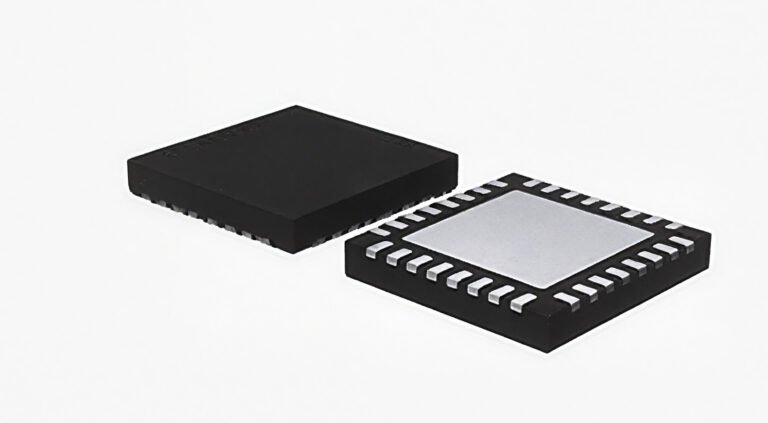
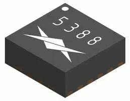
The Quad Flat No-Leads Package (QFN) is a surface-mount type of packaging characterized by its square shape and the absence of external leads. Instead, it features conductive pads (pins) for electrical connections along its four sides, with typical pin pitches of 0.65mm, 0.5mm, 0.4mm, and 0.35mm.
Due to the lack of external leads, QFN packages have a smaller footprint and height compared to Quad Flat Packages (QFP). The center of the QFN package’s bottom has a large exposed thermal pad. QFN packages do not have gull-wing leads; instead, they offer short electrical paths between internal pins and the pads, resulting in low self-inductance and internal line resistance, which provides excellent electrical performance. The exposed thermal pad serves as a heat dissipation channel, making QFN packages highly efficient at heat dissipation.
Structure of QFN Packaging
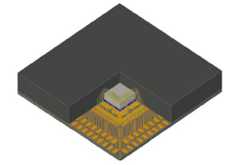
Let’s look at the wire bonding QFN package, its internal structure is as follows:

Mold and Lead Frame
QFN packaging includes a mold surrounded by a lead frame made from copper alloy with a matte tin coating. The main material of the lead frame is copper, with different grades commonly used, such as A194, C7025, and FET64.
Molding Compound
The electric molding compound is a powder mold compound composed of epoxy resin as the base resin, high-performance phenolic resin as the curing agent, and fillers such as silicon micropowder, along with various additives.
Plating Material
The plating material for the exposed pad on the bottom of the QFN package is generally pure tin or nickel-palladium-gold (NiPdAu). It provides both circuit connection to the PCB and effective heat transfer. Epoxy material secures the connection between the chip and the pad.
Die Attach
There are two main types: conductive and non-conductive. These materials can take various forms, including adhesives, die attach film (DAF), solder wire, and solder paste.
Bonding Wire
The primary types of bonding wire include copper, gold, silver, and aluminum.
Advantages of QFN Packaging
Small Size and Light Weight
Compared to other packages like SOP and TQFP, QFN offers significant advantages in size and weight. The term “package efficiency” refers to the ratio of chip area to package area approaching 1, indicating high efficiency. While SOP has a package efficiency of 0.1-0.2, QFN can achieve 0.3-0.4, and even 0.5 without a thermal pad, highlighting its high efficiency.
QFN is widely used in portable electronic devices such as mobile phones and cameras due to its small PCB space requirement.
Excellent Thermal Performance
QFN packages feature a large pad at the bottom that can be directly soldered onto the circuit board. This pad functions as a heat sink, effectively dissipating heat generated by the chip during operation, increasing the heat dissipation area and speed.
Superior Electrical Performance
QFN packages do not have external leads, leading to shorter electrical paths and lower self-inductance and internal wiring resistance, thus providing superior electrical performance.
QFN also boasts high reliability and cost-effectiveness.
Connection Technology for QFN Package
Here are some common QFN packaging techniques: Wire Bonding, Flip Chip, and Clip Connection.
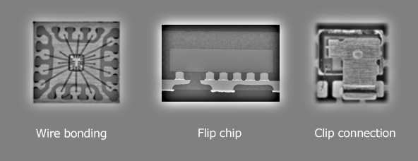
Wire Bonding
- Definition: Wire bonding is a traditional method used to connect the semiconductor chip to the package substrate. It typically uses fine metal wires (such as gold or aluminum) to connect the chip’s pads to the pads on the package or PCB.
- Relation to QFN: In a QFN (Quad Flat No-lead) package, wire bonding can be used to connect the chip’s pads to the QFN package’s solder pads. This method is often used to establish electrical connections from the chip to the PCB, especially in lower frequency or lower power applications.
- Use case: This is a widely used packaging technique, particularly in applications where smaller connection sizes and more cost-effective assembly are desired.
Flip Chip
- Definition: Flip chip is a packaging technique where the semiconductor chip is flipped over and soldered directly to the package or PCB using solder balls (or bumps) instead of traditional wire bonds. This results in a high-density connection with better thermal and electrical performance.
- Relation to QFN: Although QFN is a leadless package, flip chip technology can be used within a QFN design, particularly for the connections between the chip and the QFN package’s pads. In this case, the chip is placed upside down (flipped) and directly attached to the substrate or package.
- Use case: Flip chip is typically used in high-performance applications requiring higher density connections, such as RF circuits, processors, and other high-frequency or high-power electronics.
Clip Connection
- Definition: Clip connection refers to a method where a physical clip or clamp is used to establish an electrical or thermal connection between the chip and the package or substrate. This method is less common in QFN packages and is more often used in high-power applications or specific industries.
- Relation to QFN: Clip connection is not a typical method used in QFN packaging. However, it can be employed in certain special QFN packages, especially when there is a need to handle higher current or power, where the clip provides a strong mechanical and electrical connection.
- Use case: This connection method is used in high-power systems such as power electronics, semiconductor power devices, or situations where robust and low-resistance connections are required.
QFN Packaging Process
The QFN packaging process consists of several steps, including wafer grinding, dicing, die attach, wire bonding, encapsulation, plating, marking, and singulation. Four key steps are:
Step 1: Wafer Grinding
reduces the thickness of the wafer to fit the limited space for QFN packaging.
Step 2: Dicing
dicing separates the individual chips from the wafer.
Step 3: Die Attach
places the separated chips onto a metal carrier, which has the necessary leads.

Step 4: Wire Bonding
connects the chip’s functional pads to the package leads using an automatic wire bonder.

Step 5: Encapsulation
protects the chip and metal carrier by encasing them in epoxy resin.
Step 6: Plating
applies a layer of tin to the copper leads to prevent oxidation.

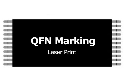
Step 7: Marking
label the chip with product names, customer logos, and batch information.
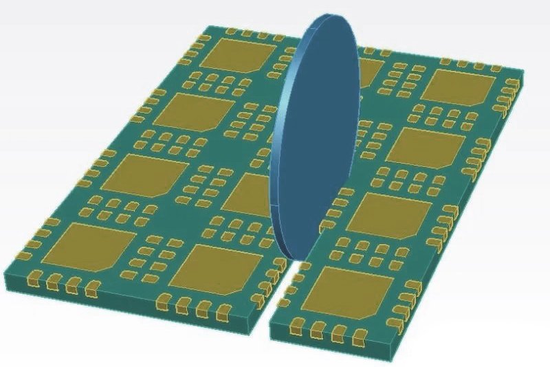
Step 8: Singulation
Singulation cuts the completed packages into individual units.
QFN Footprint Design Guidelines
When designing the PCB footprint for a QFN (Quad Flat No-lead) component, it’s crucial to ensure precise and effective layout to avoid issues in the soldering process and ensure optimal electrical and thermal performance. Here’s a detailed breakdown based on the reference content you provided, covering key aspects of QFN footprint design:
Common QFN Pitch and Example
QFN components typically come in pitches of 0.5mm, 0.4mm, and 0.35mm. For illustration, let’s focus on a 0.5mm pitch QFN component. The datasheet for such components often provides the component dimensions in a range (e.g., 0.20–0.30mm), where the most typical value might be 0.25±0.05mm. In practice, manufacturers tend to exaggerate tolerances to protect themselves, but it’s important to note that the actual dimensions may not be as wide as those listed.

Recommended PCB Footprint Design
Designing the PCB footprint for a QFN component requires careful consideration of several factors:
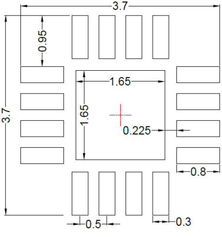
Small Pad Width: The manufacturer may recommend a pad width of 0.3mm, but based on best practices, a width of 0.27mm is suggested. A larger pad width could increase the risk of solder bridges between pads, especially when the stencil design (screen print) is not properly optimized. Additionally, the pad width should not be smaller than the lead width of the QFN component itself (typically 0.25mm).
Pad Length: The recommended pad length is generally 0.8mm, which is acceptable. For example, if the overall package width is 3mm, and the external pad length is 3.7mm, subtracting the package width (3mm) and dividing by 2 gives a 0.35mm extension for each side. This length should not exceed this value to avoid interference with nearby components, particularly the central heat dissipation pad.
Heat Sink Pad Size: The central heat sink pad should match the component’s thermal pad dimensions, often around 1.65mm. The size does not need to be larger than the manufacturer’s recommendation but should be designed with a rounded corner (especially for heat dissipation) to enhance thermal performance.
Thermal Via Design for Heat Dissipation
QFNs often have large central thermal pads that need to be connected to multiple copper layers for efficient heat dissipation. In the PCB design:
Thermal Via Size: For a 1.6mm thick PCB, it’s ideal to use vias with a hole diameter of 0.3mm. Vias should not be too large, as this can lead to solder paste leakage during reflow. Similarly, they shouldn’t be too small, as this may cause drilling issues or insufficient thermal conductivity. The via-to-via distance should be carefully considered to avoid complications during the stencil design process.
Via Count and Spacing: To effectively dissipate heat, the vias should be spaced evenly across the thermal pad. However, placing vias too closely together can cause complications with the stencil design, leading to potential issues during the soldering process. Ensure sufficient spacing between vias to allow for proper solder paste deposition and avoid solder bridging.
Stencil Design Considerations
Stencil Thickness: For a 0.5mm pitch QFN component, the recommended stencil thickness is typically 0.13mm. This thickness ensures a good balance between the solder paste volume and the ability to flow during reflow soldering.
Pad Opening for Stencil: The stencil opening should be slightly narrower than the pad width to account for the solder paste expansion. As mentioned earlier, a pad width of 0.27mm should correspond to a stencil opening width between 0.22mm and 0.24mm, ensuring sufficient solder paste volume while preventing excess paste that could lead to solder bridges.
Pad Length and Openings: The pad length for the stencil should be adjusted by 0.1mm inward, and the extension for the outer pads can range from 0.15mm to 0.25mm. The goal is to ensure an even paste layer without excess paste, especially on the smaller pads.
Thermal Pad Opening: For the large thermal pad, the stencil opening can be smaller than the actual pad size, typically around 40-60% of the total area. It’s essential to create a grid or “hatch” pattern (e.g., a crosshatch or square grid) to allow the solder paste to flow evenly while avoiding over-soldering or insufficient paste. Moreover, openings should be designed carefully to avoid overlapping any vias, which would lead to potential solder paste leakage.
Common Mistakes and Best Practices
Ignoring Tolerance in Footprint Design: Often, engineers will blindly copy the manufacturer’s recommended footprint sizes from the datasheet without considering whether the dimensions are optimized for soldering and electrical performance. It’s essential to confirm the dimensions using measurement tools, such as calipers, before finalizing the PCB design.
Over-Designing Pads: Some designers make the mistake of enlarging the pad sizes to compensate for manufacturing tolerances, but this can lead to more problems than it solves, such as bridging between pads and an increased risk of shorts during the reflow process.
Insufficient Heat Dissipation: Not paying enough attention to the thermal vias and heat dissipation design can lead to overheating of the IC, resulting in failure or malfunction. Ensuring that there are adequate vias under the thermal pad and sufficient copper area for grounding is critical for keeping the component cool and operating within safe limits.
Applications of QFN Packaging
QFN packaging is widely used in:
- Telecommunication products
- Cellular phones
- Wireless LAN
- Portable products
- Personal digital assistants (PDAs)
- Digital cameras
- Low to medium lead count packages
- Information appliances
Choosing the Right QFN Package
The choice of QFN package depends on various factors, including:
- Space Constraints: Thin and ultra-thin QFNs are best for space-limited applications.
- Thermal Management Needs: Packages with exposed thermal pads or multiple thermal vias are ideal for heat-sensitive components.
- Reliability: Packages like SWF QFN allow for better inspection, making them ideal for high-reliability applications where solder joint quality is critical.
- Assembly and Manufacturing Considerations: Some QFNs, such as those with side wettable flanks or lead-on-pad designs, simplify assembly and improve mechanical durability.

