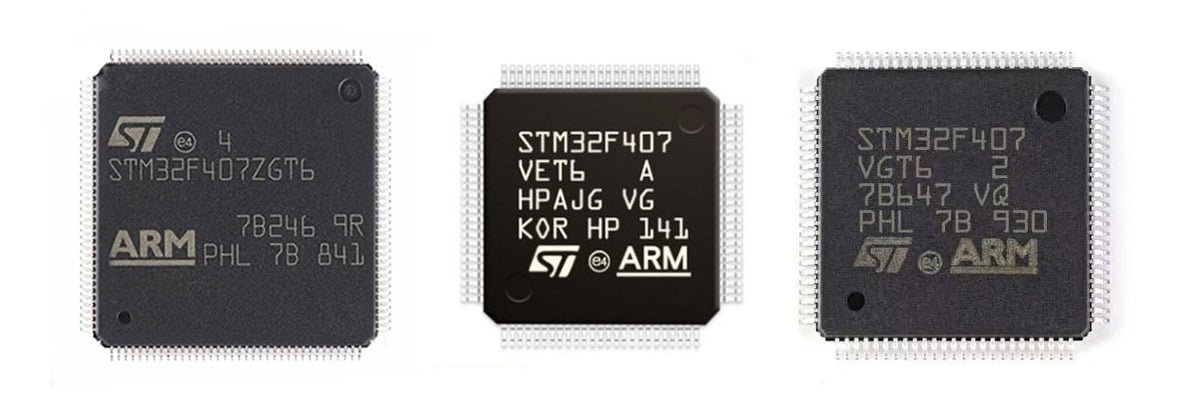
In the field of embedded systems, microcontrollers, as key components, play an important role in scenarios such as automatic control, Internet of Things, and industrial applications. The STM32F407 launched by ST Company is a high-performance and low-power 32-bit microcontroller that has attracted market attention due to its excellent functions and ease of use. In this article, we will delve into the features, specifications, application areas and development environment of STM32F407.
About STM32F407
The STM32F407 series of chips is a high-performance microcontroller launched by STMicroelectronics based on the ARM Cortex™-M4 core. It uses a 90-nanometer NVM process and ART (Adaptive Real-Time Memory Accelerator™).
STM32F407 Features
The STM32F407 is based on the ARM Cortex-M4 core, has DSP instructions and a floating-point unit (FPU), and has a clock frequency of up to 168MHz. Here are its main features:
- High Performance
Equipped with a 32-bit Cortex-M4 core, which supports floating-point operations and low clock cycle latency, it can provide high-speed computing capabilities.
- Low power Consumption
Dynamic voltage adjustment technology is used to switch between different power consumption modes and reduce system energy consumption.
- Multiple Storage Configurations
Up to 1MB Flash and 192KB RAM to meet the storage space requirements of various applications.
- Powerful Peripheral Support
STM32F407 has rich communication interfaces, such as SPI, I2C, UART, etc.; it supports up to 3 12-bit ADC converters, 2 DAC converters and high-resolution timers.
- Safety and Reliability
The built-in hardware CRC module provides real-time checksum error detection function; the Watchdog timer can monitor the system running status and prevent software deadlock.
STM32F407 Specifications
| Specification | Details |
|---|---|
| MCU Model | STM32F407ZGT6 |
| Flash Memory | 1MB |
| Clock Frequency | Up to 168MHz |
| ADC | Three 12-bit |
| DAC | Two 12-bit |
| DMA | Two DMA controllers |
| Timers | Up to 17 timers |
| GPIO | Up to 120 configurable GPIO pins |
| Interfaces | Built-in I2C, SPI, USART, I2S, CAN, and SDIO communication interfaces |
Application of STM32F407
Thanks to its flexibility and easy scalability, STM32F407 is widely used in various intelligent scenarios, including but not limited to:
- Internet of Things (IoT) devices
The low power consumption of STM32F407 makes it suitable as the core processing unit of IoT devices such as sensors and controllers.
- Industrial automation
In fields such as CNC machine tools and industrial robots, STM32F407 can be responsible for system control, data acquisition and processing, and communication with peripheral devices.
- Consumer electronics
STM32F407 can be used in consumer electronics fields such as smart homes and wearable devices to meet consumers’ requirements for performance and power consumption.
STM32F407 Development Resource
To facilitate developers, ST provides a wealth of development resources and tool support, including:
- Discovery and Nucleo series development boards
- Integrated development environments (IDEs) such as Keil uVision and IAR
- JLINK, CMSIS-DAP, ULINK or STLINK debugger
- STM32CubeF4 Software development kit based on HAL/HLL library
These resources help simplify the development process, shorten the development cycle, and enable developers to obtain technical support, share experiences and learn resources.
HAL Library
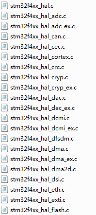
HAL library, Hardware Abstraction Layer, is actually the peripheral driver package of STM32F407. The code file is located at path:\Drivers\STM32F4xx_HAL_Driver.
CMSIS
CMSIS (Cortex Microcontroller Software Interface Standard) is a driver package officially designed by ARM. The block diagram is as follows:

With this CMSIS software package, ARM is expected to unify the peripheral drivers, DSP digital signal processing, downloaders and APIs of various mainstream RTOSs from various chip manufacturers.
STM32CubeMX is a graphics development software launched by ST in 2014 to facilitate users to configure clocks, peripherals, pins, RTOS and various middleware. The block diagram is as follows:

Through this graphics software, you can easily generate engineering code and support compilers such as MDK, IAR, and TrueSTUDIO.
STM32F407 Development Board Project
In this development experiment, we use the HAL library to light an LED or make an LED running light.
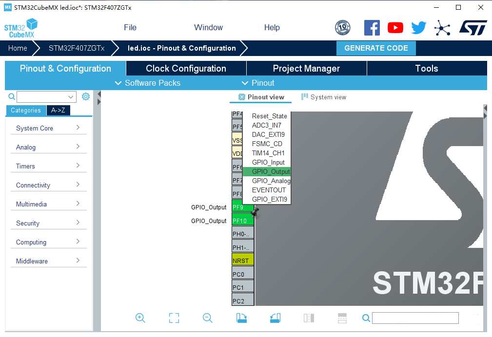
Step 1: Open STM32CubeMX, find the pin corresponding to the LED, and configure it as GPIO output.
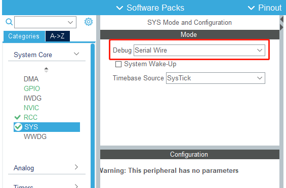
Step 2: Select Serial Wire in SYS. Only if it is selected, subsequent projects can be burned normally using st-link.
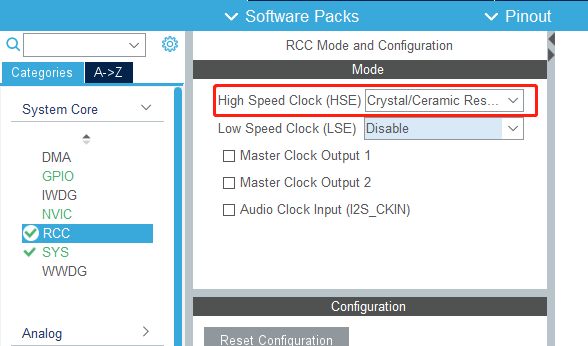
Step 3: Turn on the external clock and enable it to reach the maximum frequency of 407 168mhz.
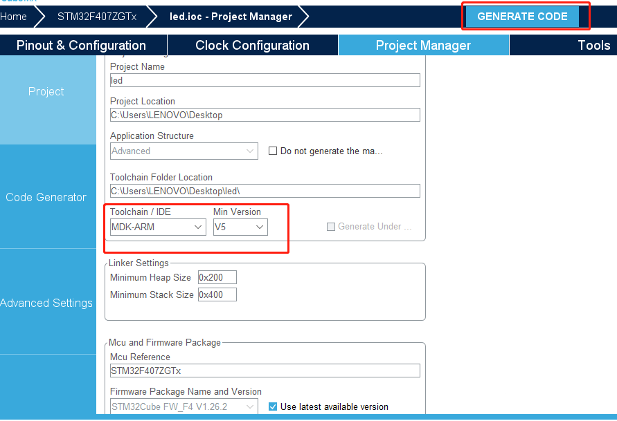
Step 4: Generate engineering code.
The generated code is as shown below, and the pin and clock configurations are all configured.
					void MX_GPIO_Init(void)
{
GPIO_InitTypeDef GPIO_InitStruct= {0}:

/*GPIO Ports Clock Enable */
_ _HAL_RCC_GPIOF_CLK_ENABLE():
_ _HAL_RCC GPIOH_CLK_ENABLE():
_ _HAL RCC GPIOA CLK_ENABLE():

/*Configure GPIO pin Output Level */
HAL_GPIO_WritePin(GPIOF, GPIO_PIN_9, GPIO_PIN_SET):
HAL_GPIO_WritePin(GPIOF, GPIO_PIN_10, GPIO_PIN_RESET):

/*Configure GPIO pins:PF9 PF10 */
GPIO_InitStruct.Pin = GPIO_PIN_9|GPIO_PIN_10:
GPIO_InitStruct.Mode = GPIO_MODE_OUTPUT_PP:
GPIO_InitStruct.Pul1 =GPIO_NOPULL:
GPIO_InitStruct.Speed = GPIO_SPEED_FREQ_LOW:
HAL_GPIO_Init(GPIOF, &GPIO_InitStruct):

/*EXTI interrupt init*/
HAL_NVIC_SetPriority(EXTI2_IRQn, 0, 0):
HAL NVIC_EnableIRQ(EXTI2_IRQn):
HAL_NVIC_SetPriority(EXTI3_IRQn, 0, 0):
HAL_NVIC_EnableIRQ(EXTI3_IRQn):
HAL_NVIC_SetPriority(EXTI4_IRQn, 0, 0):
HAL_NVIC_EnableIRQ(EXTI4_IRQn):

}
Then write the program to control the LED light in while(1) of the main function.
					while (1)
{
/* USER CODE END WHILE */

//Light up the LED
//HAL_GPIO_WritePin(GPIOF, GPIO_PIN_10|GPIO_PIN_9, GPIO_PIN_RESET);

{
//LED flashes
HAL_GPIO_TogglePin(GPIOF, GPIO_PIN_9|GPIO_PIN_10);
HAL_Delay(1000);
}
/* USER CODE BEGIN 3 */
}

