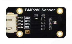
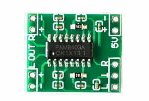
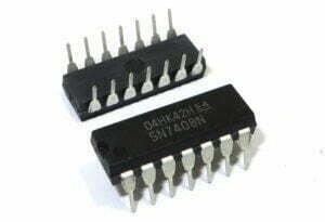
The term “pinout” is used in many fields where a device has multiple inputs or outputs. In electronics, pinouts are usually lists of numbers and letters that define how to connect cables or wires to specific places on a circuit board.
Armed with this knowledge, the next time you see a pinout you’ll know almost immediately what each column is referring to and how they relate specifically to that IC or other component.
Let’s take a look at the basics of pinout definitions, explanations, and examples.
What is a Pinout?
A pinout is a diagram or listing of the electrical connections (pins) inside an electronic component or circuit board. There is often a standard pinout used for a given component or PCB. Pinouts can be used to connect wires or to troubleshoot the operation of an electronic device.
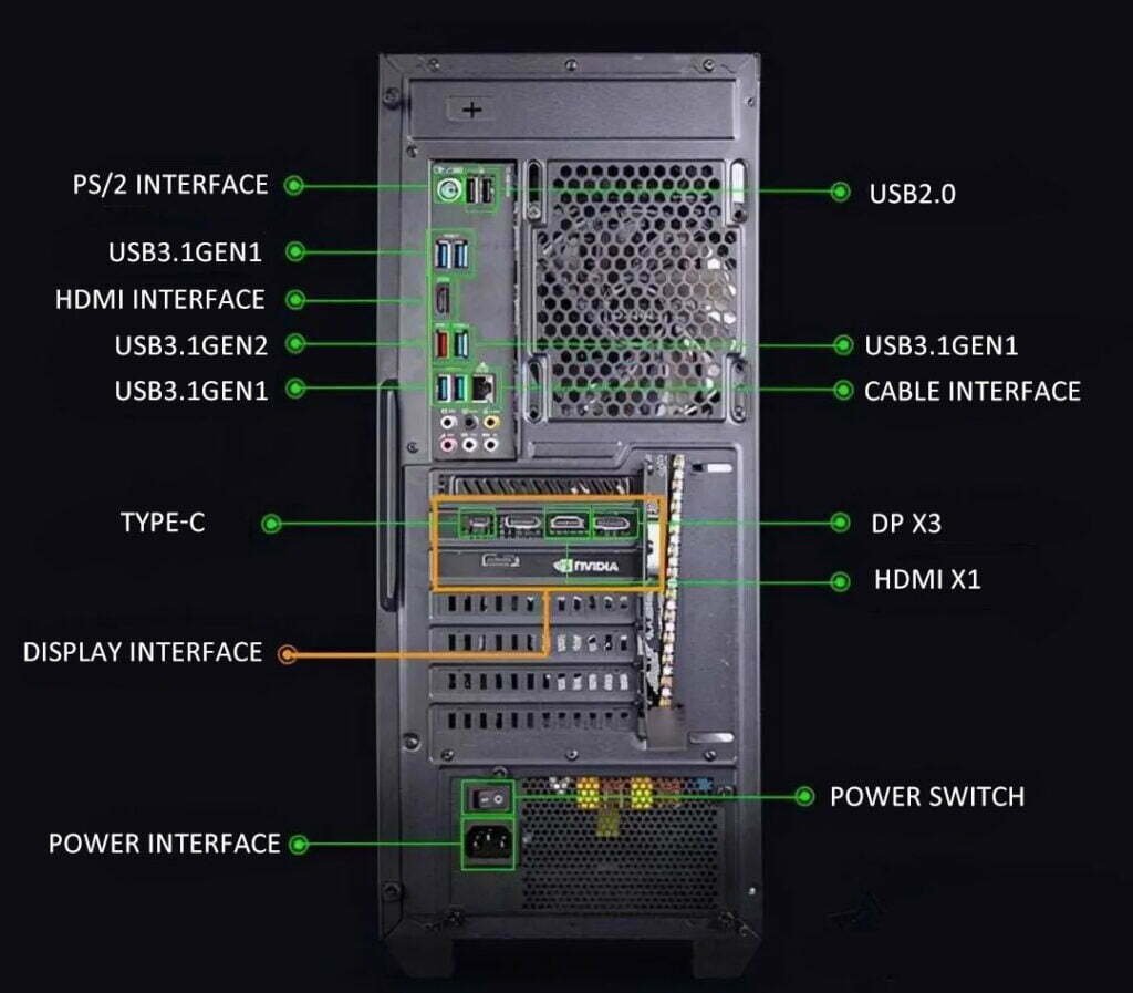
For example, a common computer power supply has a standard pinout that is used with a computer’s power button. The power supply is plugged into the computer’s motherboard, and the motherboard is plugged into the power supply unit. The power supply’s plug has two rows of pins – one row for the computer’s ground, and the other row for the computer’s +5V power. The computer’s power button is attached to the +5V power row, so a computer engineer will connect the +5V pin from the power supply to the computer’s power button. This allows the computer to turn on when the button is pressed. The computer engineer will also connect the ground pin from the power supply to the computer’s ground wires. This is necessary to safely handle the +5V current from the computer’s internal hardware.
How to Read a Pinout?
A pinout is normally presented in “parallel” format, which means that each row is for the same connections for each column. To read parallel pinouts, start at the left side of the diagram and then go row by row to the right until you’ve gone through them all.
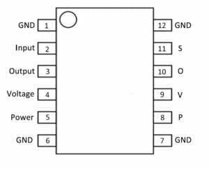
In the diagram above, you would start with the first column, which is the “ground” connection. Follow the row until you come to the “GND” connection. The second column from the left is the “input” connection, followed by “S” for “signal.” The third column is the “output” connection, followed by “O” for “output.” The fourth column is the “voltage reference” connection, followed by “V” for “voltage.” The fifth column is the “power” connection, followed by “P” for “power.” The sixth column is the “ground” connection, followed by “GND” for “ground.”
Basic Pinout Definition
- Pinout – A diagram or listing of the electrical connections (pins) inside an electronic component or circuit board.
- Ground – A connection to earth or another conductive object that is used to protect a device from electrical damage.
- Input – A connection that accepts electrical power or information.
- Output – A connection that sends electrical power or information.
- Voltage Reference – A connection that gives a precise measurement of voltage.
- Analog – Electrical signals that vary continuously over time.
- Digital – Electrical signals that have only two possible states: on or off.
Input Pinout
The first column in a pinout usually refers to input connections. The first row is the input voltage. The second row is the input current that the component will draw as it operates. The third row is the input capacitance, which is the amount of capacitance that the component draws. If the component accepts input voltage, current, or capacitance, there will be a fourth row that describes the range or acceptable values. For example, a power supply might have the following input pinout: Input Voltage: 90 – 264 VAC Input Current: 1A Input Capacitance: 5 pF
Output Pinout
The second column in a pinout usually refers to output connections. The first row is the output voltage. The second row is the output current. The third row is the output capacitance. The fourth row is the type of electrical device that the component is. For example, a power supply might have the following output pinout: Output Voltage: +5V Output Current: 1A Output Capacitance: 10 pF Output Type: Switching Regulated
Voltage Reference Pinout
The third column in a pinout usually refers to voltage reference connections. The first row is the reference voltage. The second row is the reference current. The third row is the reference capacitance. The fourth row is the number of external components that the reference requires. For example, a voltage reference might have the following pinout: Reference Voltage: 2.5V Reference Current: 10 uA Reference Capacitance: 100 pF Reference Count: 2
Analog and Digital Signal Pinouts
The fourth column in a pinout usually refers to analog and digital signal connections. The first row is the digital signal that the component accepts. The second row is the analog signal that the component accepts. The third row is the digital signal that the component provides. The fourth row is the analog signal that the component provides. For example, a voltage regulator might have the following pinout: Analog Signal: 0.1V to VOUT Digital Signal: 3.3V Analog Signal: 0.1V to VOUT Digital Signal: Open Collector
Example pinouts
Common examples of pinouts include the pinouts for a variety of connectors, such as USB, HDMI, Ethernet, and RS-232. Additionally, they can be used to describe the wiring of a circuit, such as a breadboard. Pinouts are typically referenced in diagrams, schematics, and engineering drawings to ensure that an engineer or technician is connecting components properly.
USB pinout
Generally, two power lines and two signal lines are built into the interface of the USB socket, and the signals are transmitted serially.
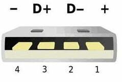
| Pin number | Name | Color |
| 1 | +5V | Red |
| 2 | D- | White |
| 3 | D+ | Green |
| 4 | GND | Black |
RS-232 Pinout
A common example of a digital pinout is the RS232 serial port pinout, which is used to connect computers to modems, printers, and other peripherals. This pinout defines 9 pins, which are used for data transmission, handshake signals, and power.
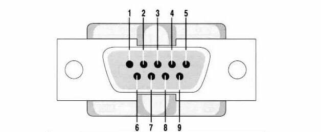
Pin number and signal:
- Data carrier detect
- Received data
- Transmitted data
- Data terminal ready
- Signal ground
- Data set ready
- Request to send
- Clear to send
- Ring indicator
PS/2 pinout
The PS/2 pinout is the layout of pins on the 6-pin mini-DIN connector used for connecting a PS/2 keyboard or mouse to a computer. The connector has 6 pins, numbered 1 to 6 from left to right. The pins carry data, power, and ground signals.

| Pin number | Name | Description |
| 1 | DATA | Key data |
| 2 | n/c | Not connected |
| 3 | GND | Ground |
| 4 | VCC | Power, +5 VDC |
| 5 | CLK | Clock |
| 6 | n/c | Not connected |
Conclusion
The term “pinout” is used to describe the arrangement of electrical connections inside an electronic component or circuit board. The connections are usually shown as a diagram or listing of columns of numbers and letters. The first column is usually for input connections, the second for output connections, the third for voltage reference connections, the fourth for analog and digital signal connections, and the fifth for power connections. Understanding pinouts will make it easier to troubleshoot circuit boards and read the documentation when working with new electronic components.

