The keyword "pic basic pro using hpwm for servo" sounds narrow, but it captures a very common embedded mistake: treating every PWM-capable peripheral as though it can drive every load in the same way. A standard hobby servo does not simply want "some PWM." It wants repeated control pulses with a useful frame period and a pulse width that represents position. That difference matters both in code and on the PCB.

Readers usually arrive at this topic from one of two directions. Either they have a PIC Basic Pro project and want to reuse the hardware PWM peripheral because it feels efficient, or they already tried HPWM and saw erratic motion, limited travel, jitter, or a servo that ignores the command. The real question is not whether PWM exists, but whether the specific timing produced by the chosen module matches what a servo expects.
What a hobby servo expects electrically
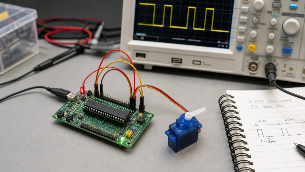
A typical hobby servo receives three connections: power, ground, and a control signal. The control signal is usually interpreted as a pulse repeated on a frame around 20 ms, with pulse width often centered in the rough range of 1 ms to 2 ms. Exact endpoints differ by servo model, but the main concept is stable: pulse width carries the command. Frequency matters only because the servo expects those pulses to repeat at a sensible rate.
That means a generic high-frequency PWM waveform is not automatically suitable. If HPWM is configured for motor-style switching frequencies, the servo sees a very different signal from what it was designed to decode. This is the same kind of confusion that shows up in broader timing and signal-interpretation work on development boards, even if the platform is not PIC-specific. The signal name alone does not guarantee signal compatibility.
Why HPWM often feels like the wrong tool
Hardware PWM modules in many microcontrollers are excellent for LED dimming, switching regulators, and motor control because they provide a repeating waveform with a defined frequency and duty cycle. Servos, however, care about an absolute pulse width inside a relatively long frame. Depending on the PIC device and the available timer divisor options, it may be awkward to choose an HPWM frequency that lands near the expected servo frame while still giving enough duty resolution to move the shaft smoothly.
That is why projects built around HPWM sometimes end up with coarse position steps, unstable centering, or confusing math that does not map cleanly to angle commands. None of that means PIC devices are poor servo controllers. It means the most convenient peripheral on paper may not be the cleanest fit for the job. This is a design-architecture choice, not a brand problem.
Where PIC Basic Pro enters the picture
PIC Basic Pro is popular because it abstracts many device details and lets users get to working code quickly. That convenience is valuable, but it can also hide the difference between command-level intent and timer-level signal generation. If you tell the toolchain to produce HPWM, you still have to ask whether the resulting waveform matches a servo's control expectations. In other words, the software command name cannot replace an oscilloscope trace and a timing calculation.
On real boards, this matters during bring-up. A servo may appear to move in one direction only, buzz around center, or twitch when other loads switch on. When that happens, engineers often blame the servo or assume the PIC pin cannot source enough current. The control pin current is rarely the issue. Far more common problems are timing mismatch, supply droop, or a poor ground reference shared with the servo power return.
Practical options that work better
The simplest safe approach is to use a servo-specific method rather than forcing HPWM into the role. Some PIC environments provide a dedicated servo command or a straightforward timer-driven pulse routine that explicitly sets high time and frame delay. Another option is to generate pulses in software from a timer interrupt if the application load is light enough and jitter can be bounded. For multi-servo systems or products that need cleaner scaling, an external servo controller may be the better architecture.
Each option makes the design intent clearer. You are no longer asking a generic duty-cycle peripheral to imitate servo semantics indirectly. You are creating the pulse width and repetition behavior the servo actually expects. That clarity also helps when documenting the circuit, reviewing how to read electrical schematics, or passing the board to someone else for test or repair.
PCB-level issues that make servo projects fail
Even with correct timing, a servo project can still behave badly if the PCB ignores power and return current realities. Servos are noisy loads compared with logic pins. Startup current, stall current, and cable-induced voltage drop can pull the supply low enough to reset the microcontroller or corrupt the control reference. The classic symptom is jitter that disappears when the servo is powered from a separate bench supply.
A robust board keeps the servo power path physically wider and electrically separate from the most sensitive controller decoupling loop. Ground should be common, but the high current return from the servo should not share a fragile trace segment with the controller reference. Bulk capacitance near the connector, local decoupling near the PIC, and sensible connector orientation all matter. These are not optional cleanup steps; they are part of whether the control method can be evaluated fairly.
When HPWM may still be acceptable
There are edge cases where HPWM can still be used successfully. If the chosen PIC device and timer configuration let you create an appropriate frame and pulse resolution, and if the math is documented clearly enough that maintenance is realistic, then HPWM may be viable. But viability should be proven on hardware, not assumed from the presence of a PWM module. Measure the output pulse width, confirm endpoint repeatability, and verify the board under load rather than only with the servo disconnected.
This is especially important in products that mix servos with other loads such as relays, displays, or communications modules. A design can look stable until the rail sags or interrupt timing shifts under real operation. General ReversePCB guidance around PCB assembly and board debugging applies here too: clear power planning and test access are what turn a barely working prototype into a dependable build.
A good engineering decision is often the simpler one
Many engineers hesitate to move away from HPWM because it feels like giving up a hardware feature they already own. In practice, using the right abstraction often lowers both firmware complexity and support cost. A timer-driven pulse routine that every maintainer can understand is usually better than a tightly constrained HPWM setup that only works because one developer memorized a timer table.
That same pragmatism applies to documentation. Label the servo connector, state the control voltage domain, document expected pulse widths, and keep the scope captures or timing notes with the project. Future troubleshooting becomes far easier when the intended behavior is explicit instead of implied.
Bottom line
PIC Basic Pro and HPWM are not automatically wrong for servo work, but they are not automatically aligned either. A hobby servo expects specific pulse width behavior inside a suitable frame, and many HPWM setups are optimized for different jobs. The safest design path is to choose a control method that speaks the servo's language directly, then back it with solid PCB power routing and ground strategy. That produces cleaner motion, less jitter, and far less confusion during debug.
Why does a hobby servo not behave like a DC motor under PWM?
A hobby servo expects position information in repeated control pulses, usually around a 20 ms frame with roughly 1 ms to 2 ms pulse width. That is different from driving a motor with a faster generic PWM duty cycle.
Can PIC Basic Pro HPWM ever be used with a servo?
It can sometimes be adapted depending on the device and timer setup, but many projects find that direct HPWM settings are awkward because the available frequency and resolution are not centered on standard servo pulse timing.
What is a safer approach for PIC Basic Pro servo projects?
A dedicated servo command, timer-driven pulse generation, or a small external servo controller is usually easier to reason about and easier to verify on hardware.
What should be checked on the PCB when a servo jitters?
Check supply droop, common ground quality, pulse integrity at the servo input, connector resistance, decoupling near the controller, and whether the control timing is stable under load.