When someone searches for Pi Pico pinout, the real goal is usually not to admire a diagram. They want to wire the board correctly, avoid a mirrored header mistake, identify which pins are safe for power, and understand which signals matter first during bring-up. That is the right way to use a pinout article.
The Raspberry Pi Pico is built around the RP2040, and its pinout is straightforward once you stop treating every edge pin as equivalent. Some pins are general-purpose digital I/O, some carry ADC roles, some are tied to power domains, and some become much more important during debugging or recovery than during a simple LED demo.

Start with the power pins before the GPIO pins
The fastest way to damage or confuse a Pico setup is to focus on GPIO numbering first and power rails second. For bring-up work, you should identify VBUS, VSYS, 3V3 output, 3V3 enable, and ground before you think about application I/O. These pins tell you how the board is being powered, whether USB is involved, and whether your external circuitry is feeding the Pico correctly.
That matters even more on custom carrier boards. A wrong assumption about VSYS or 3.3 V routing can create unstable behavior that looks like a firmware problem but is really a power-path mistake. If you are adapting the module into your own hardware, this step belongs with the same discipline used in broader PCB layout guidelines: power first, convenience second.
GPIO pins are flexible, but not identical in context
The RP2040 gives the Pico a flexible GPIO set, and that is one reason the board is popular. But flexibility should not be confused with zero constraints. Some pins are more convenient for UART use, some line up naturally with I2C or SPI plans, and some may already be committed by your debug method, your analog input needs, or your carrier board layout.
In early prototypes, engineers often pick pins based on the nearest jumper wire path. That is fine for a bench test. It becomes weak documentation if the project grows into a repeatable design. A cleaner habit is to choose pins according to interface grouping, startup behavior, and how easily the board can still be probed later.
Which pins matter most in first bring-up
If you only remember a few things from the pinout, remember these: the power rails, the main ground references, the ADC-capable pins, and the debug-related pins. On many boards that is enough to avoid the most common early mistakes. Once the power path is stable, UART or USB communication can help you test the rest.
The debug path is especially important when the board stops behaving like a beginner tutorial. USB boot mode is useful, but it is not the whole story. If a product reaches the point where firmware investigation matters, SWD access becomes much more valuable than many first-time users expect.
ADC pins deserve cleaner handling than casual GPIO wiring
The Pico exposes analog-capable inputs, and those pins should not be treated exactly like ordinary digital lines if measurement quality matters. Routing noise, reference stability, source impedance, and shared ground behavior all affect what the ADC actually reports. A board can read “something” and still deliver bad measurement quality because the analog context was ignored.
This is one reason a pinout is only the starting point. It tells you which pins can perform the function, not whether the surrounding hardware is giving those pins a clean job to do.
How the Pico pinout relates to the RP2040 itself
The Pico board is not the same thing as the raw RP2040 package. The board pinout is a mapping of RP2040 functions into a development-board form factor with onboard regulation, USB access, and easier prototyping headers. That means a useful board-level pinout article should keep one foot in the board and one foot in the underlying chip architecture.
If you need more RP2040 context, ReversePCB’s article on RP2040, Raspberry Pi’s microcontroller breakdown is the natural companion. It helps explain why the Pico feels simple on the outside while still offering a fairly capable MCU platform underneath.
Common pinout mistakes on the bench
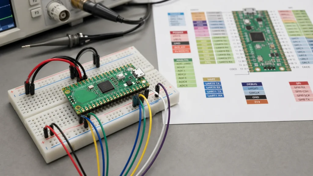
One very common mistake is mirroring the header orientation when the USB connector is facing the opposite direction from the drawing on the screen. Another is assuming every 3.3 V-related label is interchangeable. A third is forgetting that a clean ground reference matters just as much as the signal pin selection when something starts acting unstable.
People also underestimate how often the wrong problem gets blamed on “firmware.” A swapped UART pair, a poor VSYS feed, or an analog input tied into a noisy breadboard can produce symptoms that look like code bugs until the pinout and wiring are reviewed carefully.
Using the pinout in a real design review
In a real project, a pinout review is about more than making LEDs blink. It helps you check whether your chosen interfaces leave room for debug, whether the power strategy is clean, and whether the board can still be tested after it is assembled into an enclosure. That is where a development-board mindset starts to become a product mindset.
If the Pico is only a prototype controller, the pinout can stay flexible. If the Pico is serving as the basis for a custom board or a product experiment, the chosen mapping should be documented as part of the complete printed circuit board design record.
Final takeaway
A good Raspberry Pi Pico pinout reference starts with power rails and ground, then moves to GPIO, ADC, and debug functions in a deliberate order. That is much more useful than memorizing a wall of pin names without understanding which ones matter first.
If you are wiring a prototype, confirm the board orientation and the power pins before touching anything else. If you are building a repeatable design, treat the pinout as a system-level decision that affects bring-up, measurement quality, and future debugging.
Which Raspberry Pi Pico pins should I identify first?
Start with the power rails, ground pins, and the pins you expect to use for debug or analog measurement. Those are the ones most likely to cause early bring-up trouble if they are misunderstood.
Are all Pico GPIO pins interchangeable?
They are flexible, but not identical in context. Some are better choices for specific interfaces, some may already be needed for debug, and analog-capable pins deserve cleaner handling when measurement quality matters.
Why does Pico pinout confusion happen so often on breadboards?
Because the board can be mirrored relative to the on-screen diagram, and because people often focus on signal labels before confirming orientation, ground, and power rails.
Do I need to understand the RP2040 to use the Pico pinout well?
You do not need every chip detail for a simple prototype, but understanding the RP2040 helps when interface selection, ADC behavior, or debug access starts to matter.