Looking for an ultralow power microcontroller to optimize your portable measurement applications? Look no further than the Texas Instruments MSP430 family! With multiple devices featuring various sets of peripherals targeted for specific applications, the MSP430 family is a powerful and efficient solution for your needs.
What is MSP430 Microcontroller?
The MSP430 series single-chip microcomputer is a mixed-signal processor with a reduced instruction set computer (RISC). Featuring a powerful 16-bit RISC CPU, 16-bit registers, and constant generators, it is designed for maximum code efficiency. Plus, with five low power modes and a digitally controlled oscillator (DCO), you can achieve extended battery life and fast wake-up times from low-power modes to active mode in under 6µs.
Features of MSP430 Microcontroller
The MSP430 series microcontroller has the following features, which make it a powerful and versatile device that can be used for a variety of applications:
Strong processing capability:
MSP430 is a 16-bit microcontroller that uses a Reduced Instruction Set Computing (RISC) architecture with 27 core instructions and a large number of analog instructions. It has seven source operand addressing modes and four destination operand addressing modes. Additionally, it has many registers and on-chip data memory that can participate in multiple operations, ensuring efficient programming.
Fast processing speed:
MSP430 can achieve a 40ns instruction cycle time when driven by a 25MHz crystal oscillator. The 16-bit data width, 40ns instruction cycle, and hardware multiplier (which can perform multiply-and-add operations) enable it to implement some digital signal processing algorithms, such as FFT.
Ultra-low power consumption:
MSP430 has extremely low power consumption due to its unique features that help to reduce the chip’s voltage and control the clock frequency. The voltage supply range for MSP430 is 1.8-3.6V. Therefore, at 1MHz clock frequency, the chip’s current consumption is as low as 165μA, and the lowest power consumption in RAM retention mode is only 0.1μA.
Rich on-chip resources:
The MSP430 microcontroller has many on-chip peripherals such as timers, UART, SPI, I2C, ADC, DMA, I/O ports, and USB controller. These peripherals can be combined to meet various application requirements. For example, the watchdog timer ensures quick reset in case of program failure. The 16-bit timers have capture/compare function and a large number of capture/compare registers that can be used for event counting, timing generation, and PWM. The 10/12-bit hardware ADC has a high conversion rate, up to 200 kbps, making it suitable for most data acquisition applications. It can directly drive up to 160 segments of LCD and implement two 12-bit D/A conversions.
MSP430 Family Models
MSP430x15x/16x/161x series
- MSP430F155
- MSP430F156
- MSP430F157
- MSP430F167
- MSP430F168
- MSP430F169
- MSP430F1610
- MSP430F1611
- MSP430F1612
The MSP430x15x/16x/161x series takes things even further with two built-in 16-bit timers, a fast 12-bit A/D converter, dual 12-bit D/A converter, one or two universal serial synchronous/asynchronous communication interfaces (USART), I2C, DMA, and 48 I/O pins. And for memory-intensive applications and large C-stack requirements, the MSP430x161x series offers extended RAM addressing.
430F2xx series
- SP430F2012
- MSP430F2013
- MSP430F2112
- MSP430F167
- MSP430F2113
- MSP430F2122
- MSP430F2123
- MSP430F2132
- MSP430F2133
- MSP430F2232
- MSP430F2234
- MSP430F2252
- MSP430F2272
- MSP430F2274
- MSP430F2350
- MSP430F2352
- MSP430F2370
- MSP430F2471
- MSP430F2472
- MSP430F2473
- MSP430F2481
- MSP430F2482
- MSP430F2483
The 430F2xx series is a flash-based ultra-low power MCU that operates within the voltage range of 1.8V to 3.6V and offers a performance of up to 16MIPS. It includes an ultra-low power oscillator (VLO), internal pull-up/down resistors, and a low pin count option.
The ultra-low power consumption is as follows:
- 0.1μA RAM (standby mode)
- 0.3μA (hibernate mode) (VLO)
- 0.7μA (real-time clock mode)
- 220μA/MIPS (active mode)
- Quick wake-up from hibernate mode in under 1μs.
Device specifications:
- Flash options: 1KB – 120KB
- RAM options: 128B – 8KB
- GPIO options: 10, 16, 24, 32, 48, 64 pins
- ADC options: 10 and 12-bit slope SAR, 16-bit Σ-Δ ADC
- Other integrated peripherals: analog comparator, hardware multiplier, DMA, SVS, 12-bit DAC, operational amplifier.
MSP430C3xx series
- MSP430C312
- MSP430C313
- MSP430C314
- MSP430C315
- MSP430C323
- MSP430C325
- MSP430C336
- MSP430C337
- MSP430C412
- MSP430C413
- MSP430C414
- MSP430C415
- MSP430C417
- MSP430C422
- MSP430C423
- MSP430C424
- MSP430C425
- MSP430C427
- MSP430C435
- MSP430C436
- MSP430C437
The 430C3xx series is an old ROM or OTP device series that operates within the voltage range of 2.5V to 5.5V and offers up to 32KB ROM, 4MIPS, and FLL.
The ultra-low power consumption is as follows:
- 0.1μA RAM (standby mode)
- 0.9μA (real-time clock mode)
- 160μA/MIPS (active mode)
- Quick wake-up from hibernate mode in under 6μs.
Device specifications:
- ROM options: 2KB – 32KB
- RAM options: 512B – 1KB
- GPIO options: 14, 40 pins
- ADC options: 14-bit slope SAR
- Other integrated peripherals: LCD controller, hardware multiplier.
MSP430F5xx series
- MSP430F5131
- MSP430F5153
- MSP430F5173
- MSP430F5213
- MSP430F5223
- MSP430F5234
- MSP430F5242
- MSP430F5252
- MSP430F5262
- MSP430F5304
The 430F5xx series is a new flash-based product series with the lowest operating power consumption and a performance of up to 25MIPS within a working voltage range of 1.8V-3.6V. It includes an innovative power management module optimized for power consumption.
The ultra-low power consumption is as follows:
- 0.1μA RAM (standby mode)
- 2.5μA (real-time clock mode)
- 165μA/MIPS (active mode)
- Quick wake-up from hibernate mode in under 5μs.
Device specifications:
- Flash options: up to 256KB
- RAM options: up to 16KB
- ADC options: 10 and 12-bit SAR
- Other integrated peripherals: USB, analog comparator, DMA, hardware multiplier, RTC, USCI, 12-bit DAC.
How to Program MSP430?
In this project, we’ll use the MSP430F5529 board. Here’re the all steps:
- Choose a development board or programmer that is compatible with the MSP430 microcontroller. Popular options include the MSP430 LaunchPad and the MSP430 Programmer.
- Install the necessary software tools for programming the MSP430, such as Code Composer Studio or Energia.
- Connect the development board or programmer to your computer via USB.
- Write your code in a text editor or integrated development environment (IDE) and save it as a .c or .cpp file.
- Open your code in Code Composer Studio or Energia and configure the project settings as needed.
- Build the project to check for errors and generate a binary file.
- Program the MSP430 microcontroller using the programmer or development board and the generated binary file.
- Test your code on the MSP430 and make any necessary adjustments or modifications.
Requirement Tools
- Code Composer Studio (CCS)
- MSP430 Emulator: MSP-FET, MSP430-JTAG-TINY-V2, MSP-GANG, MSP430-BSL.
- MSP430 Development Board: MSP430 Launchpad, MSP-EXP430G2ET or any others.
- MSP430 Programmer: MSP430 Launchpad, MSP-FET, Black Magic Probe, etc.
Note: If you do not have access to an actual MSP430 development board, you can use an MSP430 emulator to simulate the behavior of the microcontroller on your computer. This can be a useful tool for debugging and testing your code before programming it onto an actual device.
Step 1: Setting up the Hardware
Connect the MSP430 Launchpad Development Board to your computer using the USB cable. The board should light up and the LEDs on the board should blink. This indicates that the board is powered up and functioning correctly.
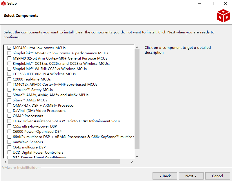
Step 2: Installing Code Composer Studio (CCS)
Download and install Code Composer Studio (CCS) from the official website. CCS is an Integrated Development Environment (IDE) that allows you to write, compile, and debug code for MSP430 microcontrollers.
Step 3: Creating a New Project
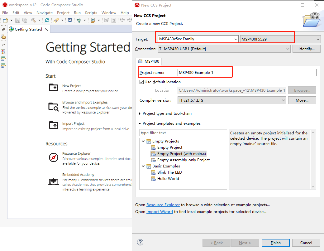
Open Code Composer Studio and create a new project. Select MSP430F5529 as the target device and choose the appropriate project template. Give your project a name and save it to your desired location.
Step 4: Writing the Code
In the CCS editor, write the following code for blinking the LED on the MSP430 Launchpad Development Board:
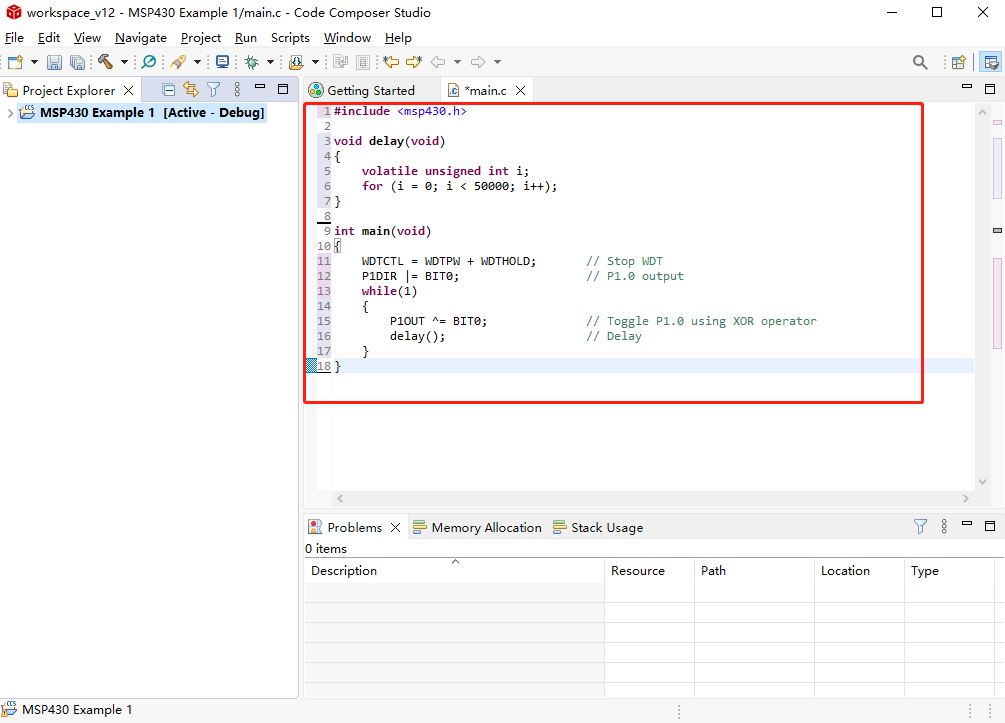
Here’s the blinking LED code:
					#include <msp430.h>

void delay(void)
{
    volatile unsigned int i;
    for (i = 0; i < 50000; i++);
}

int main(void)
{
    WDTCTL = WDTPW + WDTHOLD;       // Stop WDT
    P1DIR |= BIT0;                  // P1.0 output
    while(1)
    {
        P1OUT ^= BIT0;              // Toggle P1.0 using XOR operator
        delay();                    // Delay
    }
}
Step 5: Building and Compiling the Code
Click on the Build button in CCS to compile your code. This will generate an executable file that can be programmed onto the MSP430 microcontroller.
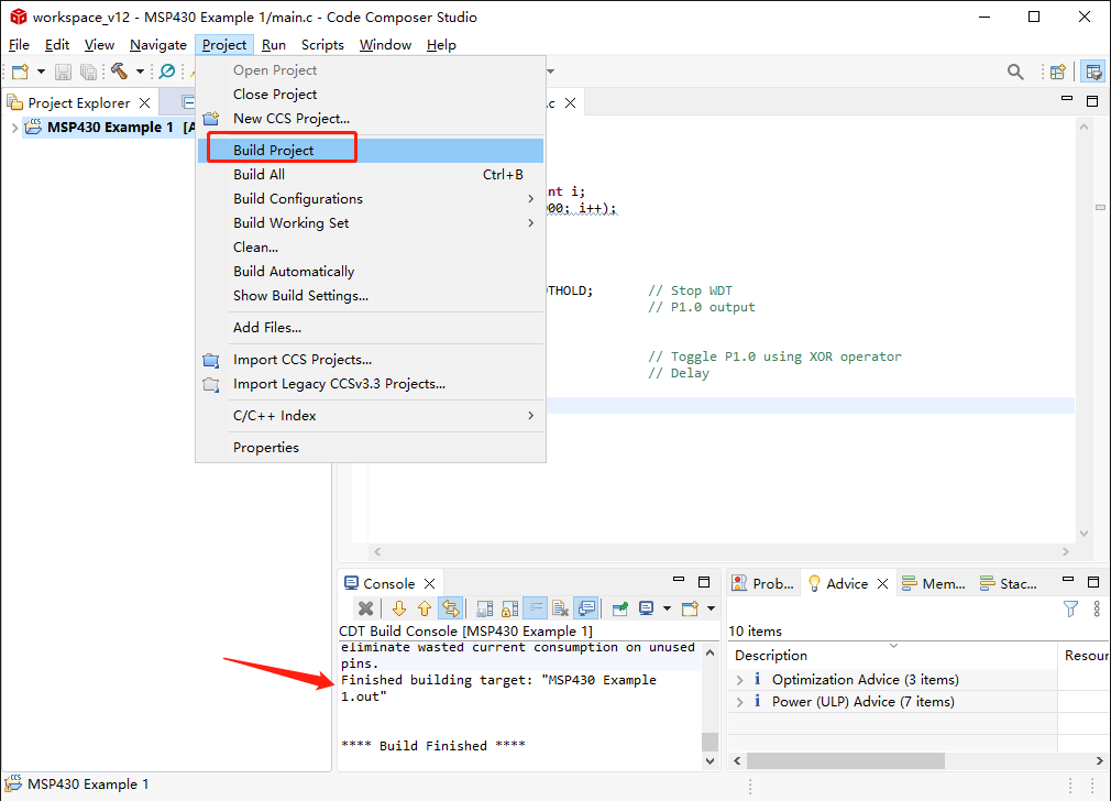
Step 6: Programming the MSP430 Launchpad Development Board
Connect the MSP430 programmer to your computer and to the MSP430 Launchpad Development Board. In CCS, click the “Run > Load” to program the code onto the microcontroller. The LED on the board should blink according to the code you have written.
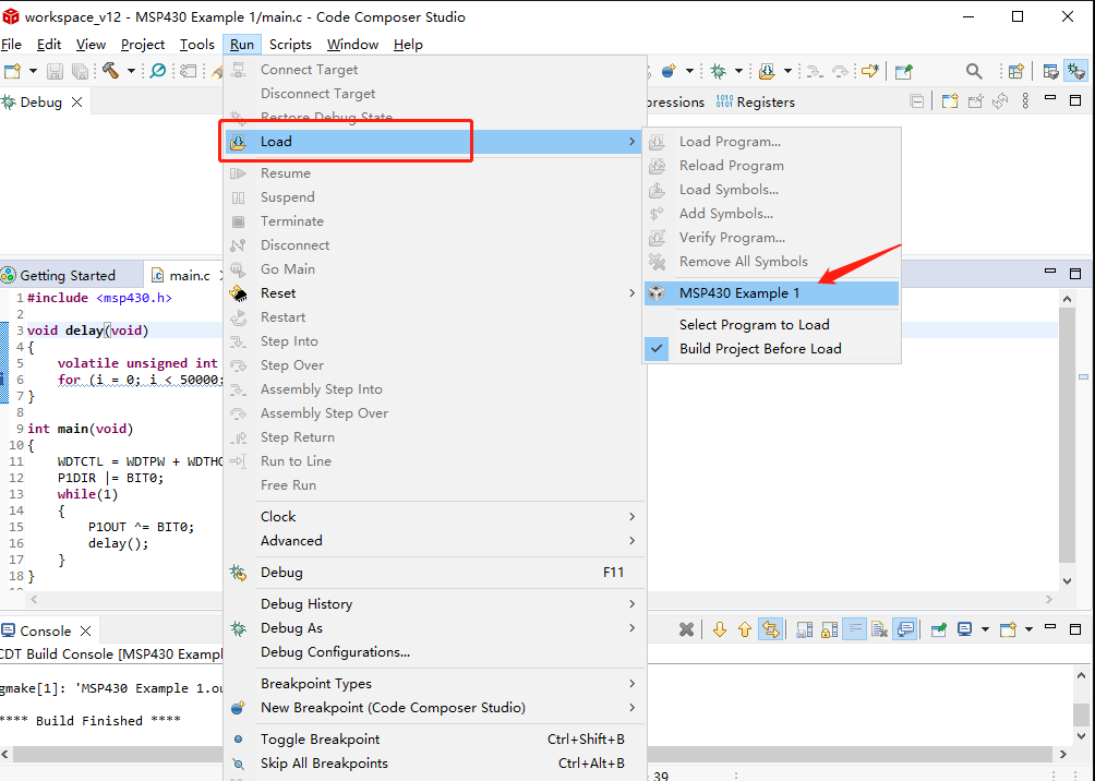
Step 7: Debugging and Troubleshooting
If you encounter any errors or issues with your code, use the debugging tools in CCS to locate and fix the problem. You can also refer to the documentation and online resources for additional help and support.
MSP430 Code Examples
ADC10 Example Code
This code demonstrates how to use the ADC10 (Analog-to-Digital Converter) module on the MSP430 to measure the voltage of an external sensor. The code initializes the ADC10 module, sets up the GPIO pins, and reads the ADC value.
					#include <msp430.h>

void init_ADC10(void)
{
    ADC10CTL0 = ADC10ON | ADC10SHT_2 | SREF_0 | ADC10IE;
    ADC10CTL1 = INCH_0 | SHS_0 | ADC10DIV_0 | ADC10SSEL_0 | CONSEQ_0;
    ADC10AE0 |= BIT0;
}

unsigned int read_ADC10(void)
{
    unsigned int result = 0;
    ADC10CTL0 |= ENC | ADC10SC;
    while(ADC10CTL1 & ADC10BUSY);
    result = ADC10MEM;
    ADC10CTL0 &= ~ENC;
    return result;
}

void main(void)
{
    WDTCTL = WDTPW + WDTHOLD;
    init_ADC10();
    while(1)
    {
        unsigned int adc_value = read_ADC10();
        // Do something with adc_value
    }
}
PWM Example Code
This code demonstrates how to use the Timer_A module on the MSP430 to generate a PWM (Pulse-Width Modulation) signal. The code initializes the Timer_A module, sets up the GPIO pins, and configures the duty cycle of the PWM signal.
					#include <msp430.h>

void init_Timer_A(void)
{
    TA0CTL = TASSEL_2 | MC_1 | ID_0;
    TA0CCR0 = 1000;
    TA0CCR1 = 500;
    TA0CCTL1 = OUTMOD_7;
}

void main(void)
{
    WDTCTL = WDTPW + WDTHOLD;
    P1DIR |= BIT0;
    P1SEL |= BIT0;
    init_Timer_A();
    while(1);
}
UART Example Code
This code demonstrates how to use the UART (Universal Asynchronous Receiver/Transmitter) module on the MSP430 to communicate with a computer or other device via serial communication. The code initializes the UART module, sets up the GPIO pins, and sends and receives data via the UART interface.
					#include <msp430.h>

void init_UART(void)
{
    P1SEL |= BIT1 | BIT2;
    P1SEL2 |= BIT1 | BIT2;
    UCA0CTL1 |= UCSSEL_2;
    UCA0BR0 = 104;
    UCA0BR1 = 0;
    UCA0MCTL = UCBRS0;
    UCA0CTL1 &= ~UCSWRST;
}

void send_UART(char data)
{
    while(!(IFG2 & UCA0TXIFG));
    UCA0TXBUF = data;
}

char receive_UART(void)
{
    while(!(IFG2 & UCA0RXIFG));
    return UCA0RXBUF;
}

void main(void)
{
    WDTCTL = WDTPW + WDTHOLD;
    init_UART();
    while(1)
    {
        char received_data = receive_UART();
        // Do something with received_data
        send_UART('X');
    }
}
MSP430 Vs MSP432
MSP430 and MSP432 are two microcontroller families from Texas Instruments. The MSP430 is a 16-bit microcontroller family, while the MSP432 is a 32-bit microcontroller family. Here is a comparison of some of their key features:
| Feature | MSP430 | MSP432 |
|---|---|---|
| Architecture | 16-bit RISC | 32-bit ARM Cortex-M4F |
| Clock Speed | Up to 25 MHz | Up to 48 MHz |
| Operating Voltage | 1.8 V to 3.6 V | 1.62 V to 3.7 V |
| Flash Memory | Up to 256 KB | Up to 512 KB |
| RAM | Up to 16 KB | Up to 64 KB |
| ADC | 10-bit, up to 16 channels | 14-bit, up to 24 channels |
| DAC | No | 2 x 12-bit |
| Timers | Up to 6 | Up to 8 |
| Communication Interfaces | UART, SPI, I2C | UART, SPI, I2C, USB, Ethernet, CAN |
| Package Types | DIP, QFP, BGA | DIP, QFP, BGA |
In summary, the MSP432 offers higher performance and more features than the MSP430, but also comes at a higher cost. The MSP430 may be a better choice for simple and low-power applications, while the MSP432 may be more suitable for complex and high-performance applications.


