MC3172 Introduction
MC3172 is a 32-bit RISC parallel multithreaded real-time processor developed by GXchip in China. It uses a new CPU working mode and software development mode. Unlike the single-threaded programming mode, the various threads of parallel multithreading run synchronously without interfering with each other, and there is no concept of priority.

MC3172 Pinout

MC3172 Features
This MC3172 microcontroller has a lot in common with the common microcontrollers we use, such as GPIO, UART, SPI, USB, CAN and other common peripherals.
But it has a very unique feature: it is a parallel multi-threaded real-time processor based on the RISC-V RV32IMC instruction set.
In other words, it has RTOS multi-threading capability, but instead of regular RTOS software scheduling, it responds in real-time at the hardware level without interrupt service routines.
- Support RV32IMC instruction set combination, single-cycle multiplication
- 64 threads running in parallel without interrupt service
- Thread resources can be configured on demand and no real-time OS required
- 100% single-cycle instructions, no branch prediction
- Support USART, SPI interface, USB2.0 host/device interface, CAN2.0B
- Up to 4 channels for input capture/output compare/PWM/pulse counting
- System time timer: 32-bit self-incrementing counter
MC3172 Specification
| Attributes | Value |
|---|---|
| Frequency | up to 200MHz |
| SRAM | 128KB |
| Core voltage | 1.62V to 1.98V |
| GPIO voltage | 1.8V ~ 3.3V |
| RC oscillator | 8MHz, 200MHz |
| External oscillator | 4MHz~40MHz |
| Input clock | 133MHz max. |
| Counters | 8 |
| I/O ports | up to 64 |
| Communication interface | 12 |
| Package | LQFP100 |
MC3172 Development Board Programming Tutorial
Before programming the MC3172 microcontroller, we need to download the development tool – MounRiver Studio, and the MC3172 Project Pack.
Download and Install the MounRiver Studio
The development software of MC3172 is MounRiver Studio, its download address:

After installing MounRiver Studio, the startup screen is as follows:

Click on load project/solution, and select our MC3172 project. This project file is inside the MC3172_Template_v1.21 file in the MC3172 data collection we just downloaded.

All the demo programs provided by the official website are located in the file “GPIO_GPCOM_TIMER_Example.c”. We will also refer to this part for our porting.
Open the thread configuration tool
In the MC3172 data collection file just downloaded, there is also a chip configuration software thread configuration tool_V1.exe. It is located in the MC3172 data collection_V1.03 \ MC3172_Template \ MC3172 directory.
The corresponding code for this software has been open source, open source address: https://gitee.com/gxchip.

Open the program download software
There is a chip program download software in the MC3172_V1.03 file downloaded from the official website, located in the MC3172_V1.03\MC3172_Template\Release directory.

MC3172 Programming - LED Blinking
With the above steps, we have prepared the MC3172 development environment, and we will design the most basic LED lighting program.
Configuring mcu resources
Open the Thread Configuration Tool_V1.exe software and setting the parameters as follow:

Click generate code, when you set the SRAM allocation, the project file MC3172.lds will be updated automatically, when you set the thread allocation thread_config.h will be updated automatically. Note: The clock source selection should be noted, the system clock source internal RC 200Mhz is turned on by default, after no clock configuration or reset, the internal 200MHz RC oscillator is used as the default CPU clock, then you can additionally choose an external 4~40MHz crystal (the evaluation board is hung with a 48m passive crystal) to drive, 8Mhz RC oscillator or external direct input clock as the kernel clock. This means that the setting here will be used directly as the kernel clock later.
Writing the program
Opening the project with the ide tool (MounRiver Studio), we can first refer to the program code in the file GPIO_GPCOM_TIMER_Example.c:
					//when main.c
GPIO_EXAMPLE(GPIOA_BASE_ADDR).

//GPIO_GPCOM_TIMER_Example.c
void GPIO_EXAMPLE(u32 gpio_sel)
{
    //enables the GPIOA clock (run|thread group|peripheral clock division setting)
    INTDEV_SET_CLK_RST(gpio_sel,(INTDEV_RUN|INTDEV_IS_GROUP0|INTDEV_CLK_IS_CORECLK_DIV2)).
    //PA0-PA7 configured as output
    GPIO_SET_OUTPUT_EN_VALUE(gpio_sel,(GPIO_PIN_7_0),GPIO_SET_ENABLE).
    //PA8-PA15 configured as input
    GPIO_SET_INPUT_EN_VALUE(gpio_sel,(GPIO_PIN_15_8),GPIO_SET_ENABLE).
    //set output high
    GPIO_SET_OUTPUT_PIN_TO_1(gpio_sel,(GPIO_PIN0|GPIO_PIN1|GPIO_PIN2|GPIO_PIN3)).
    //set output low
    GPIO_SET_OUTPUT_PIN_TO_0(gpio_sel,(GPIO_PIN4|GPIO_PIN5|GPIO_PIN6|GPIO_PIN7)).
    while(1){
        //Invert the pin level
        GPIO_SET_OUTPUT_PIN_INV(gpio_sel,(GPIO_PIN0|GPIO_PIN2)).
        u16 rx_data.
        //Get the full level of GPIOA
        rx_data=GPIO_GET_INPUT_VALUE_SAFE(gpio_sel).
        //set the value of gpio
        GPIO_SET_OUTPUT_PIN_VALUE(gpio_sel,(GPIO_PIN4|GPIO_PIN5|GPIO_PIN6|GPIO_PIN7),(rx_data>>4)).

        for (u32 var = 0; var < 5000; ++var) {
            NOP().
        }
    }
}
Following the above, write a program in void thread0_main(void) in main.c as follows:
					void thread0_main(void)
{
    // Enables the clock of GPIOA
    INTDEV_SET_CLK_RST(GPIOA_BASE_ADDR,(INTDEV_RUN|INTDEV_IS_GROUP0|INTDEV_CLK_IS_CORECLK_DIV2)).
    // Set PA0 to output mode
    GPIO_SET_OUTPUT_EN_VALUE(GPIOA_BASE_ADDR,(GPIO_PIN0),GPIO_SET_ENABLE).
    // Configure the default output to be high
    GPIO_SET_OUTPUT_PIN_TO_1(GPIOA_BASE_ADDR,GPIO_PIN0).
    while(1) {
        //Invert the pins
        GPIO_SET_OUTPUT_PIN_INV(GPIOA_BASE_ADDR,GPIO_PIN0).
        //Delay
        for (u32 var = 0; var < 5000; ++var) {
            NOP().
        }
    }
    thread_end().
}
Download the program to the MC3172
First connect the development board to the computer, and then open the development board program download software. This time a device will be recognized, click Connect Device, select MC3172.hex firmware, and click Burn Firmware. When the progress bar reaches 100%, the download is complete.

Verify the Program
To verify the LED blinking programming, we can follow these steps:
- Check the code: Make sure the programming code is correct, and it has the correct syntax for your programming language.
- Connect the LED: Connect the LED to the pin you have defined in your programming code.
- Observe the LED: If everything is correct, the LED should start blinking according to the programming code.
- Debug: If the LED is not blinking as expected, check your code again, and make sure everything is correctly connected.
MC3172 Multithreaded Parallel Execution Test
We write two threads, threads for the same configuration, two threads for each of the two IOs to flip, test code such as:
					voidLED0_GPIOA_PIN0_TEST(void)
{
//Start GPIOA and set privilege group and clock frequency
INTDEV_SET_CLK_RST(GPIOA_BASE_ADDR,(INTDEV_RUN|INTDEV_IS_GROUP0|INTDEV_CLK_IS_CORECLK_DIV2)).

//Enable the GPIOAPIN0 pin
GPIO_SET_OUTPUT_EN_VALUE(GPIOA_BASE_ADDR,GPIO_PIN0,GPIO_SET_ENABLE).

while(1)
{
//GPIOAPIN0 output 1
GPIO_SET_OUTPUT_PIN_TO_1(GPIOA_BASE_ADDR,GPIO_PIN0).

//Delay
for(u32var=0;var< 5000;++var)
{
NOP().
}

//GPIOAPIN0 output 0
GPIO_SET_OUTPUT_PIN_TO_0(GPIOA_BASE_ADDR,GPIO_PIN0).

//Delay
for(u32var=0;var< 5000;++var)
{
NOP().
}
}
}

voidLED1_GPIOA_PIN1_TEST(void)
{
//Start GPIOA and set privilege group and clock frequency
INTDEV_SET_CLK_RST(GPIOA_BASE_ADDR,(INTDEV_RUN|INTDEV_IS_GROUP0|INTDEV_CLK_IS_CORECLK_DIV2)).

//Enable the GPIOAPIN1 pin
GPIO_SET_OUTPUT_EN_VALUE(GPIOA_BASE_ADDR,GPIO_PIN1,GPIO_SET_ENABLE).

while(1)
{
//GPIOAPIN1 output 1
GPIO_SET_OUTPUT_PIN_TO_1(GPIOA_BASE_ADDR,GPIO_PIN1).

//delay
for(u32var=0;var< 5000;++var)
{
NOP().
}

//GPIOAPIN1 output 0
GPIO_SET_OUTPUT_PIN_TO_0(GPIOA_BASE_ADDR,GPIO_PIN1).

//Delay
for(u32var=0;var< 5000;++var)
{
NOP().
}
}
}

////////////////////////////////////////////////////////////


voidthread_end(void)
{
while(1).
}

////////////////////////////////////////////////////////////

voidthread0_main(void)
{
while(1){
//usercodesection
}
thread_end().
}

////////////////////////////////////////////////////////////

voidthread1_main(void)
{
while(1){
//usercodesection
LED0_GPIOA_PIN0_TEST().
}
thread_end().
}

////////////////////////////////////////////////////////////

voidthread2_main(void)
{
while(1){
//usercodesection
LED1_GPIOA_PIN1_TEST().
}
thread_end().
}
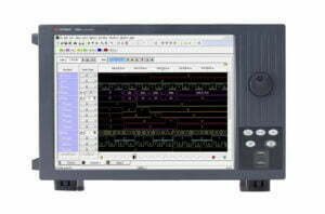
Burn the program and use a logic analyzer to capture the GPIOA_PIN0 and GPIOA_PIN1 pin level changes as follows:

As seen in the figure, the two waveforms are fully synchronized and the CPU is doing two things at the same time, achieving the same effect as RTOS multithreading.
MC3172 Programming Vs RTOS Programming
As mentioned above, the MC3172 microcontroller’s unique feature is a parallel multi-threaded real-time processor. It solves these problems such as the underlying cumbersome porting process, time-consuming scheduling, etc., which occur during RTOS development. Through the underlying hardware-level real-time response, it can achieve true “real-time operation”.
Here is a code example of MC3172 microcontroller parallel multi-threaded programming:
					void thread0_main(void)
{
    while(1)
    {
      /// Application code
    }
}

void thread1_main(void)
{
    while(1)
    {
      /// Application code
    }
}

void thread2_main(void)

void thread3_main(void)

------
We all know that the RTOS underlying scheduling threads will take several us (different processor time consumption), but the MC3172 processor is almost close to 0 time consumption. This means that the MC3172 threads are running in parallel at their own stable frequency, with no switching overhead or jitter.
Also, the MC3172 processor’s peripheral response data is more real-time. For example: UART serial port to receive external data, multiple threads can receive and respond to the serial data in parallel. (Ordinary microcontroller is generally interrupt priority, will “pause” to respond to low priority serial data, blocking the case, but also lost data)
Conclusion
The MC3172 microcontroller is a very unique processor that I have seen in China. It solves some of the problems that exist with RTOS, and improves the efficiency of chip programming.
So, if you are using RTOS development and meeting problems such as scheduling delays between threads, you can try the MC3172 microcontroller.