STM32L432 Overview
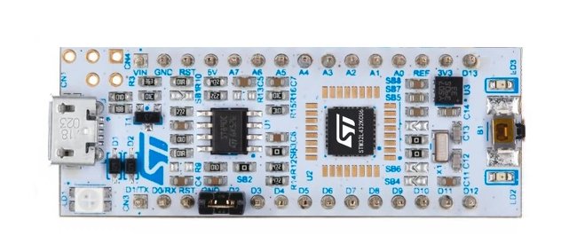
The STM32L432 is an ultra-low-power microcontroller developed by STMicroelectronics. It is based on the ARM Cortex-M4 core and is designed for energy-efficient embedded systems. Combining powerful computational capabilities with low power consumption, it is ideal for IoT devices and portable applications.
Specifications
The STM32L432 series offers the following key technical features:
Processor Core:
- ARM Cortex-M4 32-bit RISC processor
- Runs at up to 80 MHz with single-cycle multiply and hardware division support
- Integrated Floating Point Unit (FPU) and Digital Signal Processing (DSP) instructions
Memory:
- 256 KB Flash (on-chip programmable memory)
- 64 KB SRAM
- Support for external memory expansion
Low-Power Features:
- Multiple low-power modes: Sleep, Stop, and Standby
- Dynamic power consumption: only 37 µA/MHz at 80 MHz operation
- Stop mode current: approximately 250 nA
- Wide voltage range: 1.8V to 3.6V with built-in power management
Interfaces and Peripherals:
- GPIO: Up to 51 general-purpose input/output pins
- Communication interfaces: USART/UART, I2C, SPI, CAN, USB 2.0 (Full Speed)
- Timers: General-purpose, low-power, and advanced timers (PWM output)
- ADC/DAC: 12-bit ADC (16 channels) and 12-bit DAC
- Built-in oscillator and real-time clock (RTC) support
Package Options:
- Available in various packages (e.g., LQFP, UFBGA, WLCSP) to suit different size requirements.
Application
Thanks to its low power consumption and high performance, the STM32L432 is widely used in the following fields:
IoT Devices:
- Smart home systems (e.g., smart locks, temperature and humidity sensors)
- Wearable devices (e.g., fitness trackers, health monitoring equipment)
Industrial Control:
- Data acquisition and control systems
- Smart meters and sensor nodes
Portable Devices:
- Battery-operated devices (e.g., portable medical instruments)
- Low-power displays (e.g., e-ink screen controllers)
Consumer Electronics:
- Toys and robotics
- Smart remote controllers
Security and Encryption Applications:
- Hardware AES encryption support for secure communication
Advantages
- Low Power Design: Ideal for battery-powered devices requiring extended operational lifetimes.
- Cost-Effective: Provides excellent performance at a competitive price point.
- Robust Development Ecosystem: Supported by STM32CubeMX, STM32CubeIDE, and a comprehensive suite of libraries and tools from ST.
- Reliability: Industrial-grade design, with high temperature tolerance and wide operating voltage range.
GPIO Control Using NUCLEO-L432KC Board
In this example, we’ll introduce the principles of the LED circuit on the STM32L432KC board, create a new project using STM32CubeMX, and master programming techniques to achieve LED blinking.
Required Materials
- NUCLEO-L432KC development board
- USB cable for power and communication
- LED (if external LED is needed)
- Resistor (e.g., 220Ω for external LED)
- STM32CubeMX software
- Development environment such as MDK5 (Keil) or STM32CubeIDE
Step1: Create a New Project Using STM32CubeMX
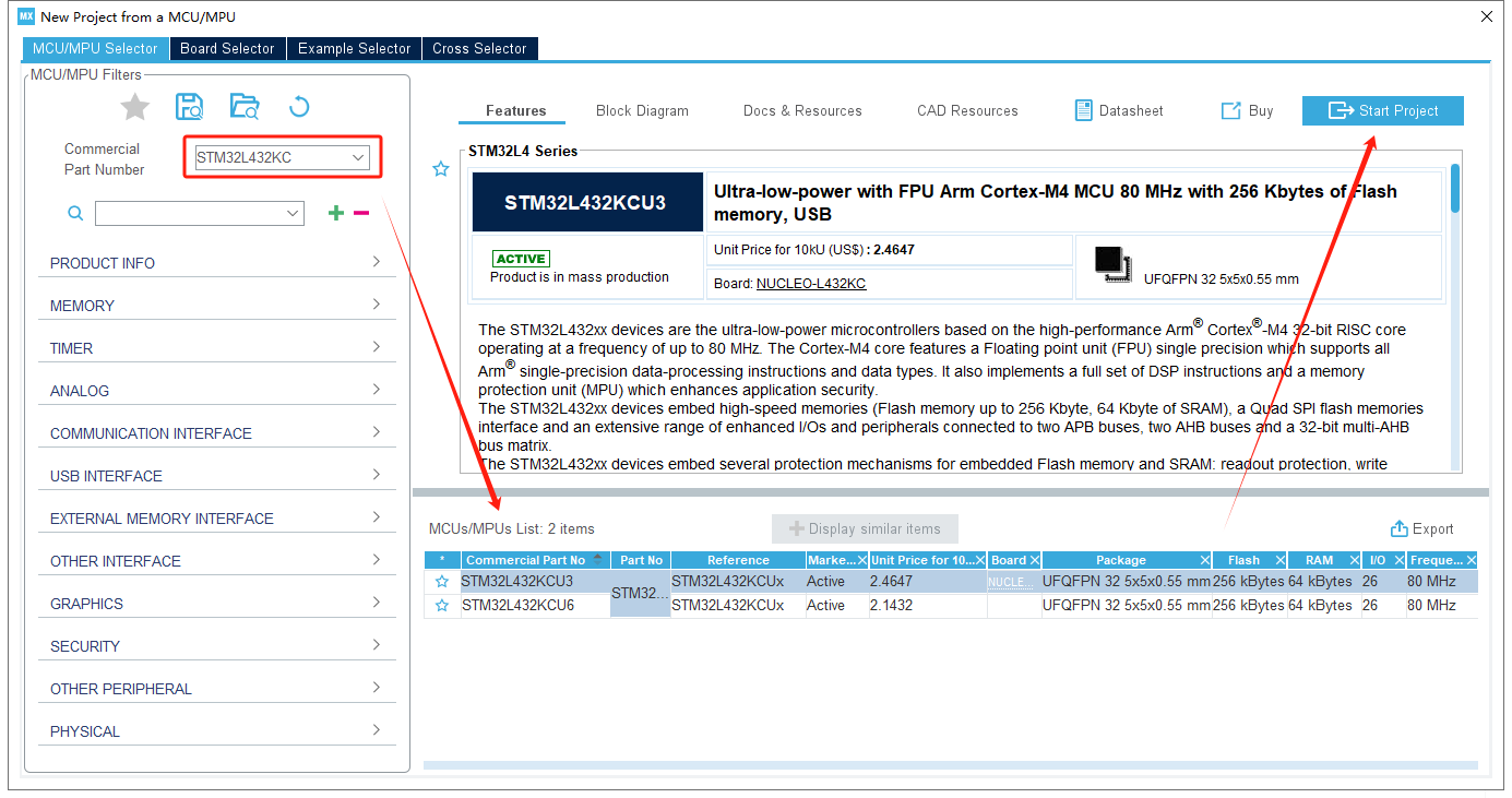
At first, please select the STM32L432KC MCU and create a new STM32CubeMX project.
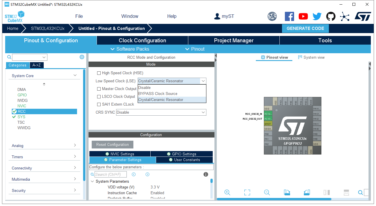
Next, we configure the oscillator for STM32L432KC. From the schematic, the external low-speed crystal oscillator is connected to PC14 and PC15. Configure these GPIOs in “Crystal/Ceramic Resonator” mode.
Explanation of Oscillator Modes:
BYPASS Clock Source: The chip bypasses the internal clock-driving component and directly uses an external clock signal.
Crystal/Ceramic Resonator: Utilizes an external passive crystal combined with the MCU's internal clock-driving circuit, offering higher precision but requiring startup time.
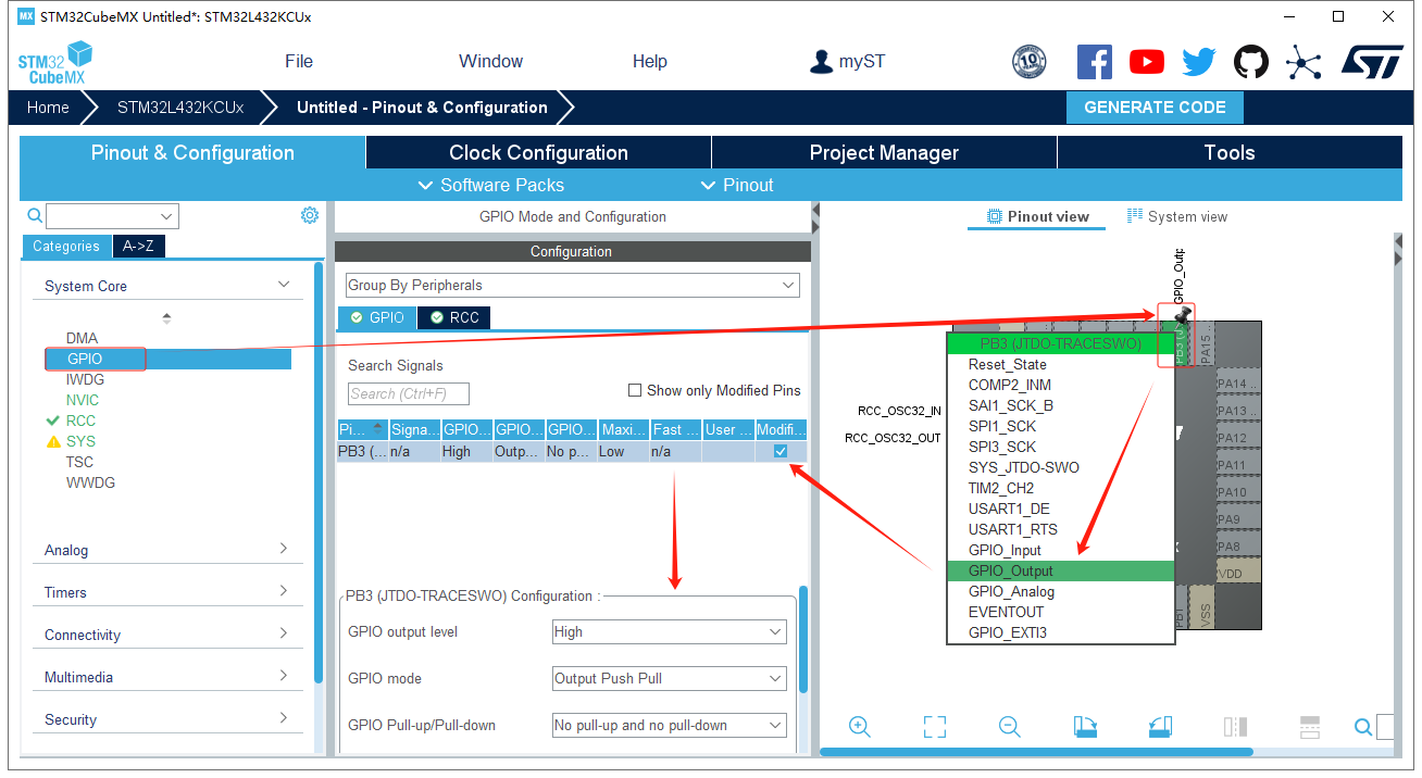
Configure the GPIO for the LED. Set PB3 as “GPIO_Output” mode with the following parameters:
- Push-pull output
- Default low-level output (LED off initially)
- No pull-up or pull-down resistors
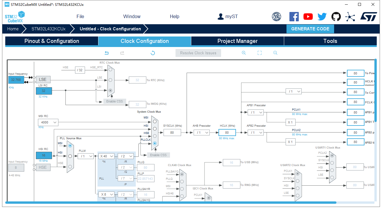
Configure the clock. For simplicity, set the system clock to 80 MHz, allowing STM32CubeMX to auto-configure the required settings.
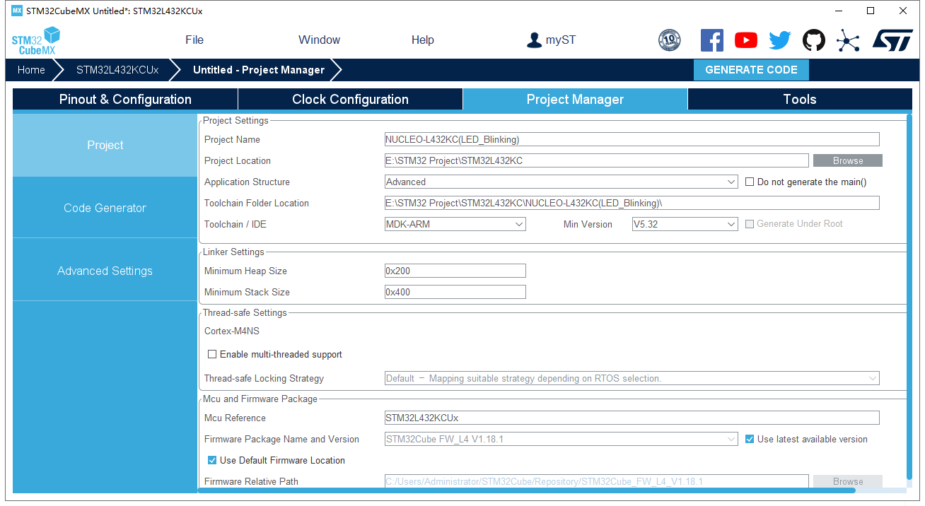
Set code generation preferences in the Project interface:
- Name the project and select the development tool (e.g., MDK5).
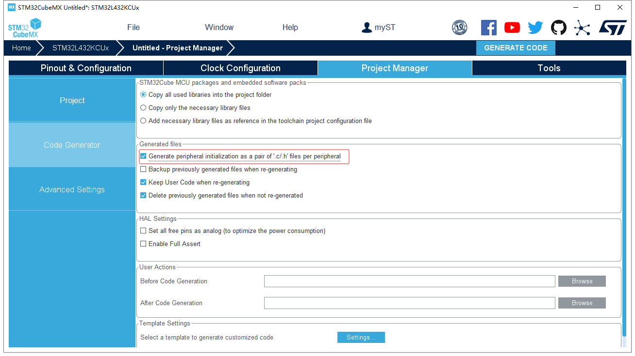
- Enable “Generate peripheral initialization as a…” to create separate
.cfiles for peripherals (e.g., GPIO, I2C, SPI).
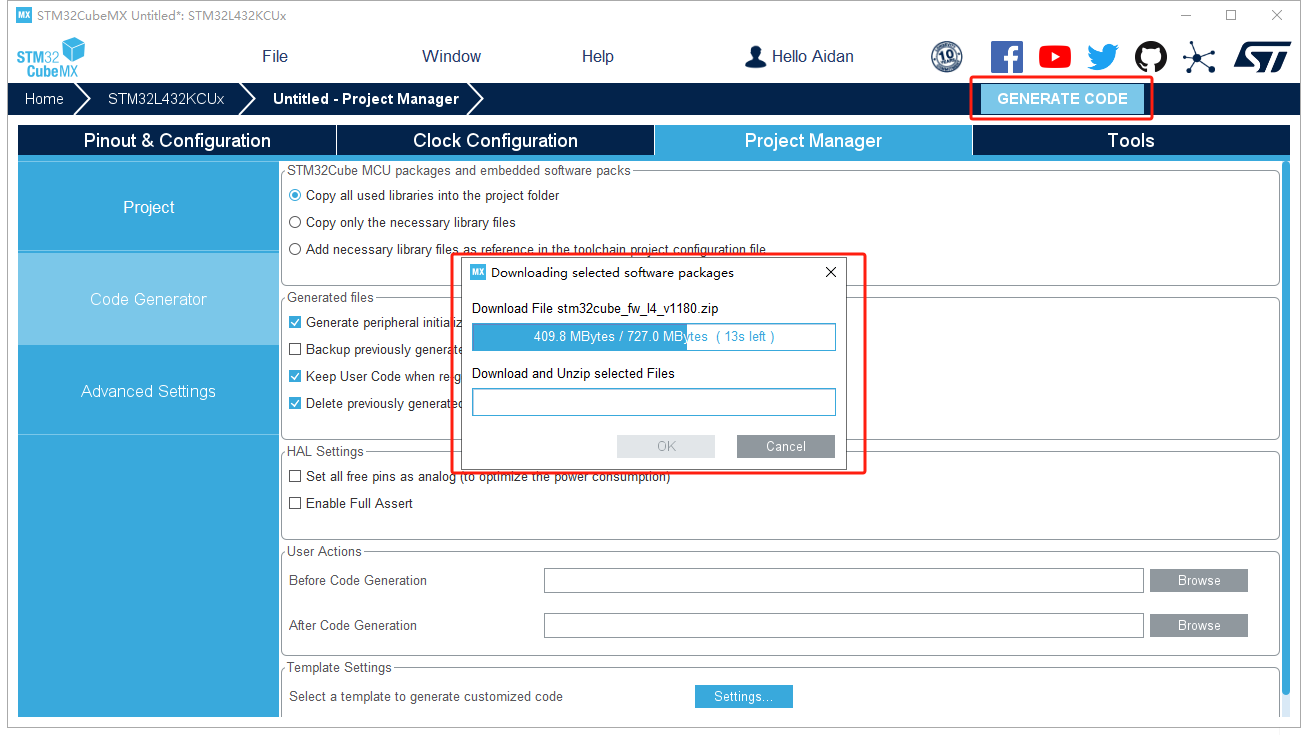
After setting all the project options, we can generate the project. If it’s the frist time you use the STM32CubeMX, you need to download the software packages as below:
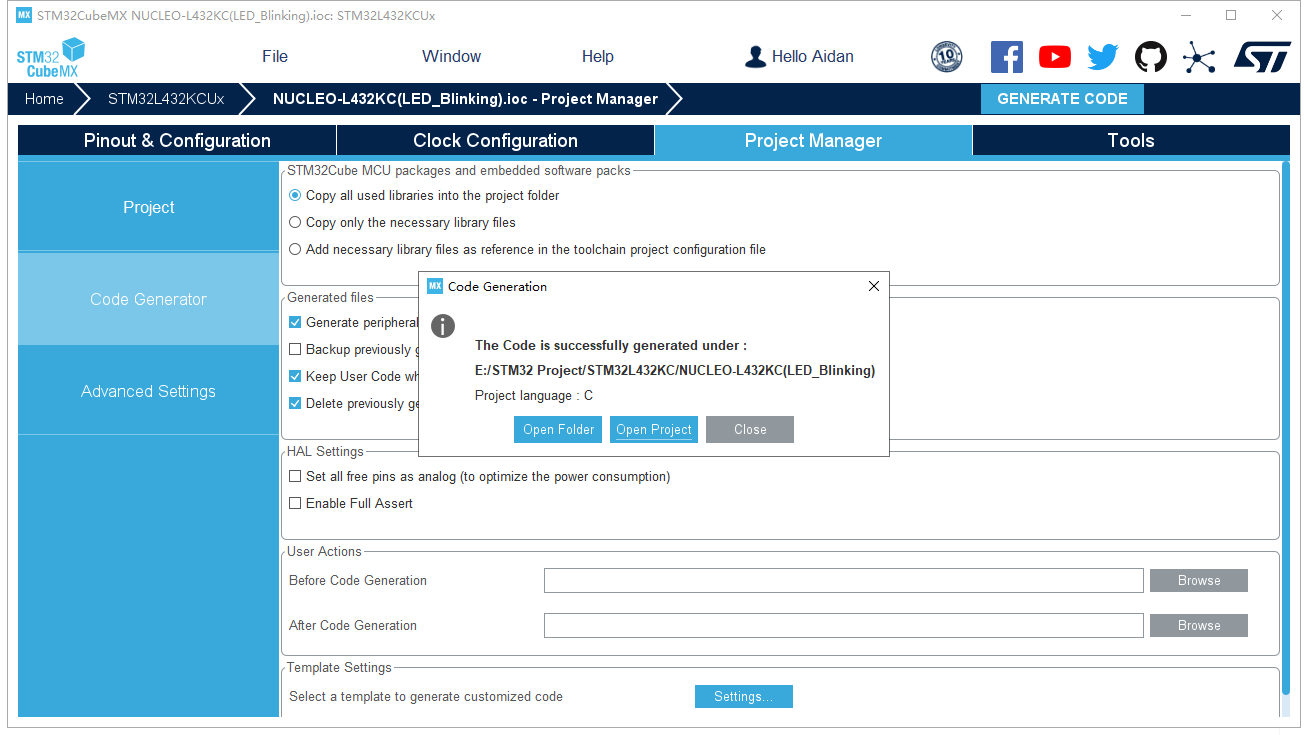
Next, keep on code generation, and after successful generation, open the project folder.
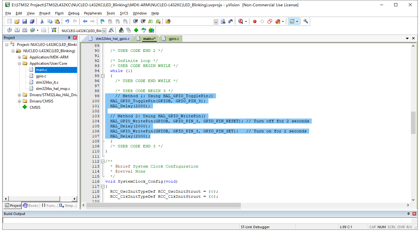
The folder will contain both STM32CubeMX and MDK5 project files, allowing convenient modifications in STM32CubeMX. Now we can launch the “NUCLEO-L432KC(LED_Blinking)” project under MDK-ARM folder.
Step2: Write LED Blinking Code
Locate the required functions in STM32 HAL files:
HAL_GPIO_TogglePin()andHAL_GPIO_WritePin()instm32l4xx_hal_def.h.HAL_Delay()instm32l4xx_hal.h.
Implement the below code to blink the LED every 2 seconds:
					/* USER CODE BEGIN WHILE */
while (1)
{
  // Method 1: Using HAL_GPIO_TogglePin()
  HAL_GPIO_TogglePin(GPIOB, GPIO_PIN_3);
  HAL_Delay(2000);

  // Method 2: Using HAL_GPIO_WritePin()
  HAL_GPIO_WritePin(GPIOB, GPIO_PIN_3, GPIO_PIN_RESET); // Turn off for 2 seconds
  HAL_Delay(2000);
  HAL_GPIO_WritePin(GPIOB, GPIO_PIN_3, GPIO_PIN_SET);   // Turn on for 2 seconds
  HAL_Delay(2000);
}
/* USER CODE END WHILE */
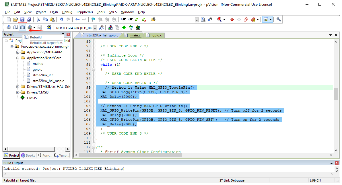
Compile the code and ensure there are no errors.
Step3: Configure Flashing Parameters
The NUCLEO-L432KC board has an integrated STLINK/V2-1 debugger and programmer.
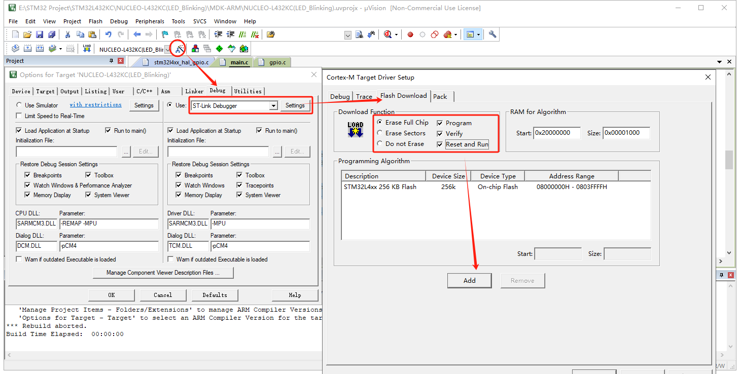
- Configure the project to use ST-LINK for downloading.
- Set the flashing parameters as shown in the STM32CubeMX interface, then download the program.

