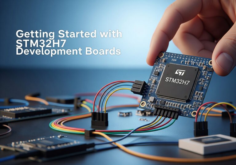
The STM32H7 series is a powerhouse in the world of microcontrollers. Known for its high performance, it is a favorite among developers.
These microcontrollers are designed by STMicroelectronics, a leader in the semiconductor industry. They offer impressive processing speeds and advanced features.
STM32H7 development boards are perfect for projects needing real-time performance and high computational power. They cater to a wide range of applications.
Whether you’re an engineer or a hobbyist, STM32H7 boards provide the tools you need. They are versatile and adaptable to various project requirements.
In this guide, we’ll explore the STM32H7 series in detail. From features to programming, you’ll learn everything you need to get started.
What is the STM32H7 Microcontroller Series?
The STM32H7 series stands out as a top choice for high-performance microcontrollers. These chips boast impressive processing capabilities, making them a go-to solution for demanding tasks.
Powered by the ARM Cortex-M7 core, they can reach speeds up to 480 MHz. This makes them ideal for applications requiring significant computational power and efficiency.
Key attributes of the STM32H7 series include:
- Up to 2MB of Flash memory and 1MB of RA
- Advanced connectivity options like Ethernet, USB, and CAN
- Support for FreeRTOS and other real-time operating systems

These microcontrollers cater to various applications, including industrial automation, consumer electronics, and automotive systems. Their robust design supports long-term reliability, critical in many industries.
With robust security features, STM32H7 microcontrollers ensure data integrity and safety. Features like hardware cryptography and secure boot make them suitable for secure applications.
In summary, the STM32H7 series delivers versatility, performance, and reliability. It is an excellent choice for developers aiming to build efficient and secure embedded systems.
Popular STM32H7 Development Boards
The STM32H7 series offers a variety of development boards, each catering to different project requirements. These boards come in various form factors and configurations, making them versatile for numerous applications.
STM32H743ZI Nucleo board
One notable option is the STM32H743ZI Nucleo board. It’s popular among developers due to its user-friendly design and extensive peripheral support. This board is ideal for motor control and industrial automation projects. Its compatibility with the Arduino ecosystem enhances its flexibility for prototyping.

STM32H750B-DK Discovery kit
Another popular board is the STM32H750B-DK Discovery kit. This board is tailored for applications requiring enhanced graphics and touch interfaces. It features an LCD display, making it suitable for human-machine interface (HMI) applications.

STM32H7S78-DK Discovery kit
The STM32H7S78-DK Discovery kit stands out as a powerful platform for high-performance applications. Equipped with advanced graphics capabilities and a high-resolution display, it is perfect for developing sophisticated user interfaces and rich multimedia experiences. This kit also offers robust connectivity options and a comprehensive set of peripherals, making it highly versatile for demanding embedded projects that require both processing power and advanced visual output.

STM32H7 vs ESP32: A Detailed Comparison
When choosing a microcontroller, comparing STM32H7 and ESP32 is vital. Both have unique strengths and serve different needs.
STM32H7 stands out with its exceptional processing power. It boasts up to 480 MHz, making it suitable for intensive computations. In contrast, ESP32 offers moderate processing power but integrates Wi-Fi and Bluetooth, making it a popular choice for IoT.
Developers often choose STM32H7 for its extensive peripheral and interface support. It is ideal for applications requiring multiple communication protocols like I2C, SPI, and UART. On the other hand, ESP32 shines in wireless connectivity. Its robust Wi-Fi and
Bluetooth capabilities are suitable for smart devices and home automation.
Here’s a quick comparison of features:
STM32H7
CPU: Arm Cortex-M7 (Single or Dual Core, up to 600 MHz)
RAM: Up to 1.4 MB SRAM, plus other RAM
Flash Memory: Up to 2 MB embedded Flash
Connectivity: Ethernet, USB, SPI, I2C, UART, CAN, etc.
Peripherals: ADC, DAC, Timers, PWM, RNG, LCD Controller, etc.
Power Consumption: As low as 32 µA in Stop mode, total current consumption as low as 4µA
Main Applications: High-performance industrial control, graphical interfaces, real-time processing, complex embedded systems
Ecosystem: Extensive STM32 ecosystem, including STM32CubeMX, HAL libraries, etc.
Price: Typically higher
ESP32
CPU: Xtensa LX6 Dual-Core (up to 240 MHz)
RAM: 520 KB SRAM
Flash Memory: 448 KB ROM (built-in), external Flash expandable
Connectivity: Wi-Fi (802.11 b/g/n), Bluetooth (v4.2 BR/EDR & BLE), SPI, I2S, I2C, UART, SD/SDIO, etc.
Peripherals: ADC, DAC, Touch Sensors, PWM, IR Remote, Pulse Counter, etc.
Power Consumption: Deep sleep current 5 µA
Main Applications: Internet of Things (IoT), wireless communication, smart home, low-power applications
Ecosystem: ESP-IDF, Arduino IDE, MicroPython, etc.
Price: Typically lower
Summary:
The **STM32H7** series are high-performance microcontrollers designed for applications requiring significant processing power, rich peripherals, and real-time capabilities, such as advanced industrial control, graphical user interfaces, and complex embedded systems. They generally feature more memory and higher clock frequencies.
The **ESP32** series, on the other hand, is a microcontroller with integrated Wi-Fi and Bluetooth, making it ideal for Internet of Things (IoT) applications, wireless communication, and scenarios requiring low-power connectivity. Its strengths lie in its wireless connectivity features and more accessible price point.
The choice between these microcontrollers depends on your specific project needs, including performance requirements, power budget, connectivity demands, and cost considerations.
Getting Started with STM32H7 Programming
Diving into STM32H7 programming can be both exciting and rewarding. This series offers high processing power, making it a favorite for complex applications. Understanding how to program these microcontrollers is crucial for leveraging their full potential.
STM32CubeIDE is the primary development environment for STM32H7 programming. It provides an integrated suite of tools for coding, debugging, and deploying applications. This IDE supports multiple programming languages, including C and C++, catering to various developer preferences.
STM32H7 supports several real-time operating systems (RTOS), including FreeRTOS. An RTOS allows developers to build applications with precise control timing, crucial for real-time systems. Incorporating an RTOS can enhance the performance of your STM32H7 projects significantly.
To get started, follow these steps:
- Install STM32CubeIDE: Download and set up the IDE.
- Set Up the Toolchain: Configure compilers and necessary plugins.
- Learn the Basics: Explore the STM32CubeIDE interface and features.
- Example Projects: Start with provided templates to understand the workflow.
- Explore Libraries: Utilize middleware and peripheral libraries.
Programming Example-Blinking an LED
In this case, you’ll learn setting up a basic project to blink an LED. This fundamental “Hello World” of embedded programming will introduce you to GPIO (General Purpose Input/Output) control, the STM32CubeIDE development environment, and the essential steps of configuring, coding, compiling, and flashing your STM32H7 board.
By the end of this guide, you will have successfully made an LED on your development board blink, laying a solid foundation for more complex projects.
Hardware Requirements
Before we begin, ensure you have the following hardware:
- STM32H7 Development Board:
- Any STM32H7 Discovery Kit (e.g., STM32H750B-DK, STM32H7S78-DK)
- Or an STM32H7 Nucleo Board (e.g., STM32H743ZI Nucleo)
- (Most of these boards have at least one user-programmable LED onboard, typically connected to a GPIO pin like PC13, PB0, PB1, or PE1)
- USB Type-A to Micro-B/Type-C Cable: To power the board and connect it to your computer for programming/debugging.
- Personal Computer: Running Windows, macOS, or Linux.
Software Requirements
You’ll need the following software installed on your computer:
- STM32CubeIDE: This is STMicroelectronics’ official Integrated Development Environment, which includes the GCC compiler, debugger, and the STM32CubeMX graphical configuration tool. It’s free and highly recommended.
- Download from: https://www.st.com/en/development-tools/stm32cubeide.html
Step-by-Step Tutorial
Part 1: STM32CubeIDE Project Setup
Launch STM32CubeIDE: Open the application. If it’s your first time, it might ask for a workspace location. Choose a suitable directory.

- Create a New STM32 Project:
Go to File > New > STM32 Project.

After the system initializing STM32 target selector, you can specify your exact STM32H7 microcontroller in the “Target Selection” window.

You can use the “Part Number” search bar. For example:
- If you have an STM32H743ZI Nucleo, type
STM32H743ZI. - If you have an STM32H750B-DK, type
STM32H750VB. - If you have an STM32H7S78-DK, type
STM32H7S78.
- If you have an STM32H743ZI Nucleo, type
Select your specific device from the list and click Next.

- Project Name and Settings:
- Project Name: Enter a descriptive name, e.g.,
H7_LED_Blink. - Targeted Project Type: Leave as
Empty. - Click
Finish. - If prompted to initialize all peripherals with their default mode, click
Yes. This will open the STM32CubeMX configuration interface.
- Project Name: Enter a descriptive name, e.g.,

Part 2: STM32CubeMX Configuration (within STM32CubeIDE)
Once the project is created, the .ioc file (STM32CubeMX configuration file) will open. This is where you graphically configure your microcontroller.
Pinout & Configuration:
Identify the LED Pin: Refer to your development board’s user manual to find which GPIO pin the onboard user LED is connected to. Common pins include
PC13(for Nucleo-144 boards),PB0,PB1, orPE1.Configure the GPIO Pin:
Find the identified pin on the chip diagram or in the “Pinout View” (e.g.,
PC13).Left-click on the pin and select
GPIO_Output. The pin will turn green, indicating it’s configured as an output.Optional – User Label: It’s good practice to label your pins. You can right-click the pin and select
Enter User Label. TypeOnboard_LED(or a similar descriptive name).

- Configure GPIO Settings:
- In the “Pinout & Configuration” tab, expand
System Core > GPIO. - Find the row corresponding to your configured LED pin (e.g.,
PC13). - In the “GPIO output level” column, set it to
Low. (We want the LED to start OFF). - Ensure “GPIO mode” is
Output Push Pull. - Leave other settings (Pull-up/Pull-down, Maximum output speed) as default for this basic example.
- In the “Pinout & Configuration” tab, expand
- Configure GPIO Settings:

- System Core -> SYS Configuration:
- In the “Pinout & Configuration” tab, expand
System Core > SYS. - Under “Configuration”, set the
Debugoption toSerial Wire. This is crucial for debugging and flashing.
- In the “Pinout & Configuration” tab, expand
- Clock Configuration:
- Go to the
Clock Configurationtab. - For a simple LED blink, the default clock settings generated by CubeIDE are usually sufficient. No changes are typically needed here unless you require very specific clock speeds.
- Go to the
- Project Manager & Code Generation:
- Go to the
Project Managertab. - Verify the
Project NameandToolchain/IDE(should beSTM32CubeIDE). - Generate Code: Click the
Generate Codebutton (the gear icon orProject > Generate Code). - If prompted to save changes, click
Yes. - This action will generate all the necessary initialization code for your project based on your CubeMX configuration.
- Go to the

Part 3: Code Implementation
Now that the basic project structure and peripheral configurations are set up, we’ll write the actual blinking logic.
Navigate to
main.c:In the Project Explorer panel (left side of STM32CubeIDE), navigate to:
H7_LED_Blink(your project name)> Core > Src > main.cDouble-click
main.cto open it in the editor.
Locate the
while(1)Loop:Scroll down in
main.cuntil you find the/* USER CODE BEGIN 3 */and/* USER CODE END 3 */comments within thewhile(1)loop. This is where you will add your application code.
Add Blinking Logic:
Inside the
while(1)loop, add the following two lines of code:
					/* USER CODE BEGIN 3 */
HAL_GPIO_TogglePin(Onboard_LED_GPIO_Port, Onboard_LED_Pin); // Toggle the LED state
HAL_Delay(500); // Wait for 500 milliseconds (0.5 seconds)
/* USER CODE END 3 */
Explanation of the code:
HAL_GPIO_TogglePin(): This is a function from the STM32Cube HAL (Hardware Abstraction Layer) library. It changes the state of the specified GPIO pin from high to low, or low to high.Onboard_LED_GPIO_Port: This is a macro automatically generated by CubeMX, representing the GPIO port (e.g.,GPIOCif your LED is on PC13).Onboard_LED_Pin: This is a macro automatically generated by CubeMX, representing the specific pin number (e.g.,GPIO_PIN_13if your LED is on PC13).
HAL_Delay(500): This HAL function creates a blocking delay for the specified number of milliseconds. Here, it pauses execution for 500ms (half a second).
Part 4: Build, Flash, and Verify
Finally, let’s compile your code, load it onto the board, and see the LED blink!
Connect Your Board:
Plug one end of your USB cable into the appropriate USB port on your STM32H7 development board (usually labeled “USB ST-LINK” or “USB USER”).
Plug the other end into a USB port on your computer. Your computer should recognize the board.
Build the Project:
Go to
Project > Build Projector click the hammer icon in the toolbar.Check the “Console” view for any errors or warnings. A successful build will show “Build Finished” and indicate no errors.
Flash the Program to the Board:
Go to
Run > Debugor click the Debug icon (a green bug).STM32CubeIDE will automatically configure the debugger settings (ST-LINK).
Click
OKorSwitchif prompted to switch to the Debug perspective.The program will be compiled (if not already), downloaded to your STM32H7 board’s flash memory, and the debugger will start.
Observe the LED Blinking:
Once the flashing is complete and the program starts running, you should see the user LED on your STM32H7 development board start blinking on and off, with a half-second interval.
Exit Debugging:
To stop the debugger and let the program run freely, click the red square “Terminate” button in the Debug perspective, then click the “Run” (green play) button. Alternatively, simply disconnect the USB cable and reconnect it (the program is already in flash).
To switch back to the C/C++ perspective, click
Window > Perspective > Open Perspective > C/C++.
Part 5: Conclusion & Next Steps
Congratulations! You’ve successfully completed your first STM32H7 embedded programming project. You’ve learned how to:
Create a new project in STM32CubeIDE.
Configure GPIO pins using STM32CubeMX.
Write basic C code using HAL functions.
Compile, flash, and run your program on the STM32H7 board.
Next Steps:
Experiment with Delay: Change the
HAL_Delay()value to make the LED blink faster or slower.Control Multiple LEDs: Configure another GPIO pin as output and make multiple LEDs blink simultaneously or in sequence.
Button Input: Configure a GPIO pin as input to read the state of a user button and control the LED based on button presses.
Explore More Peripherals: Look into using UART for serial communication, Timers for precise timing, or ADC for analog readings.
STM32H7 programming benefits from extensive libraries and middleware provided by STMicroelectronics. These resources simplify the process of adding complex functionalities to your applications. With robust community support and detailed documentation, getting started with STM32H7 programming is smooth and achievable.
Essential Tools and Software for STM32H7 Development
Embarking on STM32H7 development requires a suite of essential tools and software. These resources ensure an efficient workflow and comprehensive project management. Choosing the right tools greatly enhances the development process.
The first step involves selecting a compatible Integrated Development Environment (IDE). STM32CubeIDE is ideal for STM32H7 programming. It integrates multiple functions, offering coding, compiling, and debugging capabilities in one platform. This convenience is unmatched for developers.
In addition to STM32CubeIDE, consider using STM32CubeMX. This graphical tool simplifies the configuration of microcontroller settings. It allows easy management of peripherals and pin configurations, streamlining the setup phase of your project.
Here’s a list of essential tools for STM32H7 development:
- STM32CubeIDE: Comprehensive development environment.
- STM32CubeMX: Simplifies peripheral configuration.
- Debugger/Programmer Tools: ST-LINK/V2 for on-chip debugging.
- Libraries and Middleware: Enhance application functionality.
ST-LINK/V2 is crucial for in-circuit debugging and programming. It allows developers to seamlessly connect their STM32H7 development boards to computers, providing detailed insight and control during troubleshooting. Utilizing these tools ensures your STM32H7 development is both effective and enjoyable.
Conclusion
The STM32H7 series offers unparalleled performance and versatility. It’s a solid choice for projects needing robust processing power and precise control. With its array of features, it caters to various industries and applications.
Before selecting STM32H7, assess your project’s specific requirements. Consider factors like processing speed, connectivity, and budget. If high performance and advanced features are paramount, the STM32H7 is likely well-suited to meet your needs.