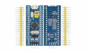
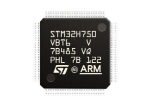
PCB Prototye Cases
How to Read PCB Schematics: A Guide to Layout and Signal Path Analysis
Decoding PCB schematics may look nifty, but mastering it takes some finesse. Learn the lingo—symbols, connections, and all the tricks. Get it right, and you’ll never look at circuits the same way!
RLC Circuit – Phasor, Sine Wave, and Animation Analysis
What is an RLC circuit? An RLC circuit is an electrical circuit that contains a resistor (R), inductor (L), and capacitor (C) connected in series or parallel. These components work
Simple PCB Schematic Examples: A Beginner’s Guide
A PCB (Printed Circuit Board) schematic is the logical and visual representation of a circuit. It is the first step in the electronic product design process. In earlier times, designers
Common File Types for Schematic Drawings of PCBs
In the design and manufacturing of Printed Circuit Boards (PCBs), choosing the most appropriate layout file to convey schematic and manufacturing instructions is added to the degree of accuracy of
Threshold s/350e Power Amplifier Schematic
Are you in search of a high-end power amplifier that can take your audio experience to the next level? Then look no further than the Threshold s/350e power amplifier. But
Electrical Schematic Diagram
Schematic Diagram Definition A schematic diagram is a graphical representation of an electrical circuit or system using standardized symbols and notations. It is used to communicate the design of the
PCB Schematic Design – Step by Step Guide
PCB Schematic Design Software Recommendation When selecting a PCB schematic design software, it is important to consider the features and capabilities of the particular software. Some of the most popular
How to Create Schematic Symbol?
What is the schematic Symbol? A schematic symbol is a graphical representation of an electrical or electronic component. There are many schematic symbols in schematic library. And the schematic library
About Well Done
Well Done Technology was established in 2008, focus on PCB reverse engineering, PCB assembly, PCB design and manufacturing. Our technical team of more than 20 people includes senior engineers with rich experience.