Introduction to PIC16F17146
PIC16F17146 is a microcontroller chip that belongs to the PIC16F family, which is renowned for its high performance and low power consumption. It is commonly used in a variety of electronic devices, such as consumer electronics, automotive applications, and industrial control systems. The PIC16F17146 offers a wide range of features, including multiple communication interfaces, analog-to-digital converters, and plenty of memory for storing program instructions and data. This versatile chip enables developers to create sophisticated applications with ease, thanks to its flexible architecture and extensive set of peripherals. For instance, it can be used in automotive systems to control engine functions, or in smart home devices to manage various home automation tasks.
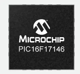
PIC16F17146 Features
- C Compiler Optimized RISC Architecture
- Enhanced midrange core with 49 instructions, 16 stack levels
- Flash program memory with self-read/write capability
- Low-Current Power-on Reset (POR)
- Programmable Brown-Out Reset (BOR) with Fast Recovery
- Low-Power Brown-out Reset (LPBOR)
- Idle and Hibernate Low Power Modes
- Windowed Watchdog Timer (WWDT)
- Peripheral Module Disable (PMD)
- Peripheral Pin Select (PPS)
- Enhanced power on/off reset
- Configurable Power-up Timer (PWRT)
PIC16F17146 Specification
| Attribute | Value |
|---|---|
| Model | PIC16F17146 |
| Architecture | RISC |
| Temperature Range | -40°C to 85°C |
| Frequency | up to 32MHz |
| Voltage | 1.8V to 5.5V |
| Size | 6.5 x 9.4 x 1.5mm |
| Memory | up to 28 KB |
| EEPROM | up to 256 Bytes |
| SRAM | up to 2 KB |
| Timer | 3 x 16-bit, 3 x 8-bit |
| PWM | 4 x 16-bit |
| CLC | 4 |
| DAC | 2 x 8-bit |
| ADC | 1 x 12-bit |
| USART | 1 |
| I2C | 1 x 7/10-bit |
| SPI | 1 |
| Operational Amplifier | 1 |
| I/O Port | up to 35 pins |
| Package | 14-Pin PDIP, SOIC, TSSOP; 16-Pin VQFN; 20-Pin PDIP, SOIC, SSOP, VQFN |
How to Program the PIC16F17146 Curiosity Nano Development Board?

Requried tools:
- MPLAB® X Integrated Development Environment (IDE)
- PIC16F17146 Curiosity Nano Board *1
- USB Cable * 1
PIC16F17146 Curiosity Nano - LED Blinking Test
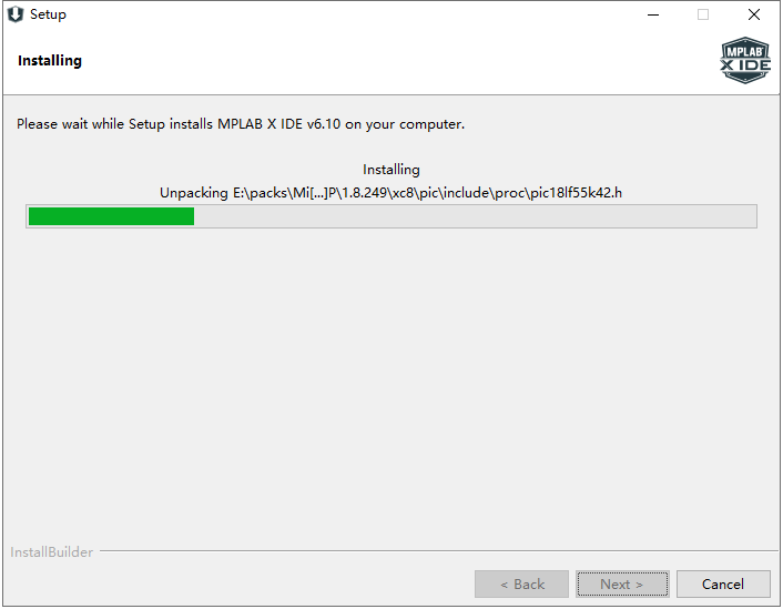
At first, download and install the MPLAB X IDE v6.10 from Microchip site:
https://www.microchip.com/en-us/tools-resources/develop/mplab-x-ide#

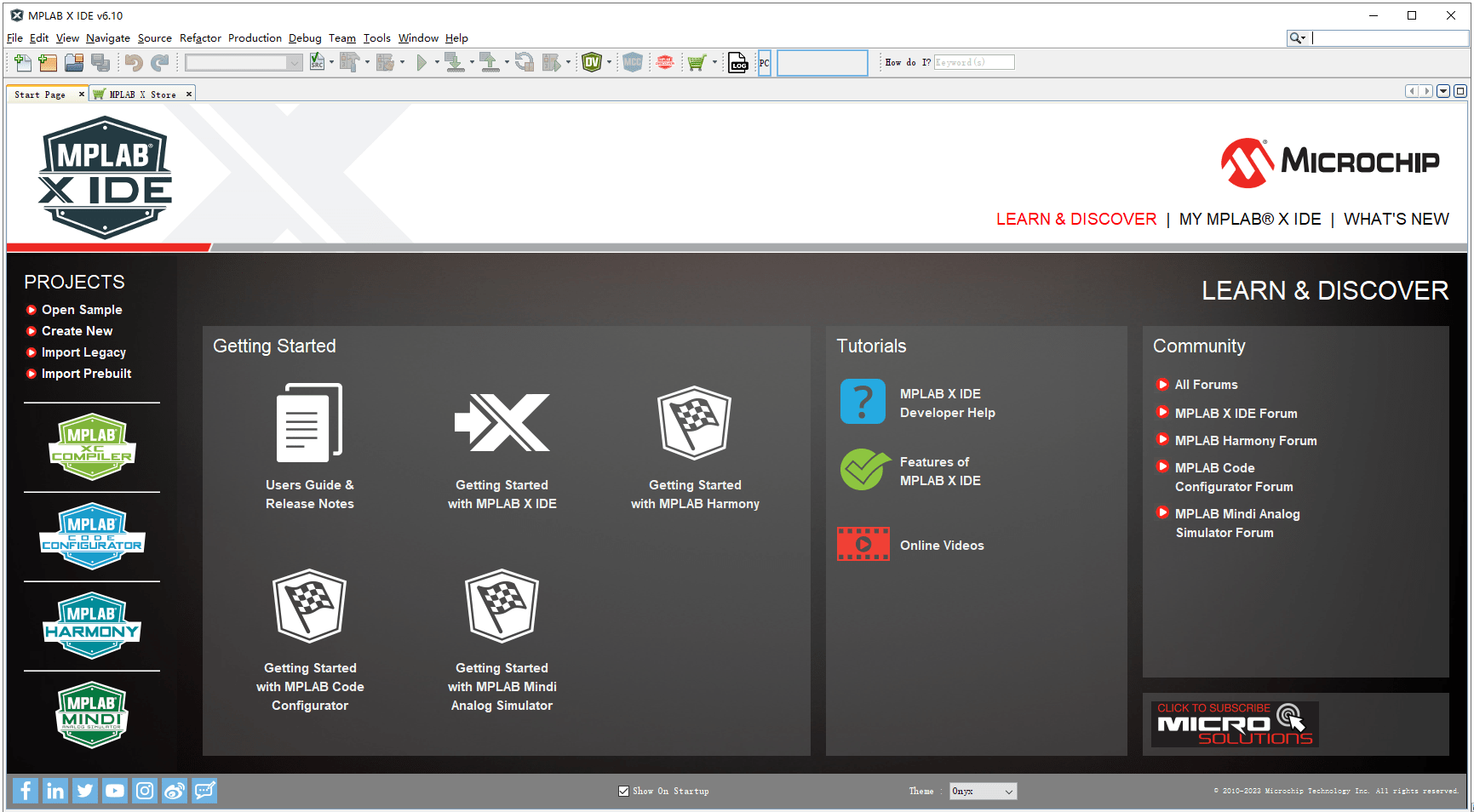
After setup the MPLAB® X IDE, we can see a user-friendly interface. If you are a beginner, there’re some getting started tutorials for you.
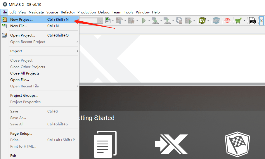
Continue to our project, Click the “File > New Project” to create a new project.
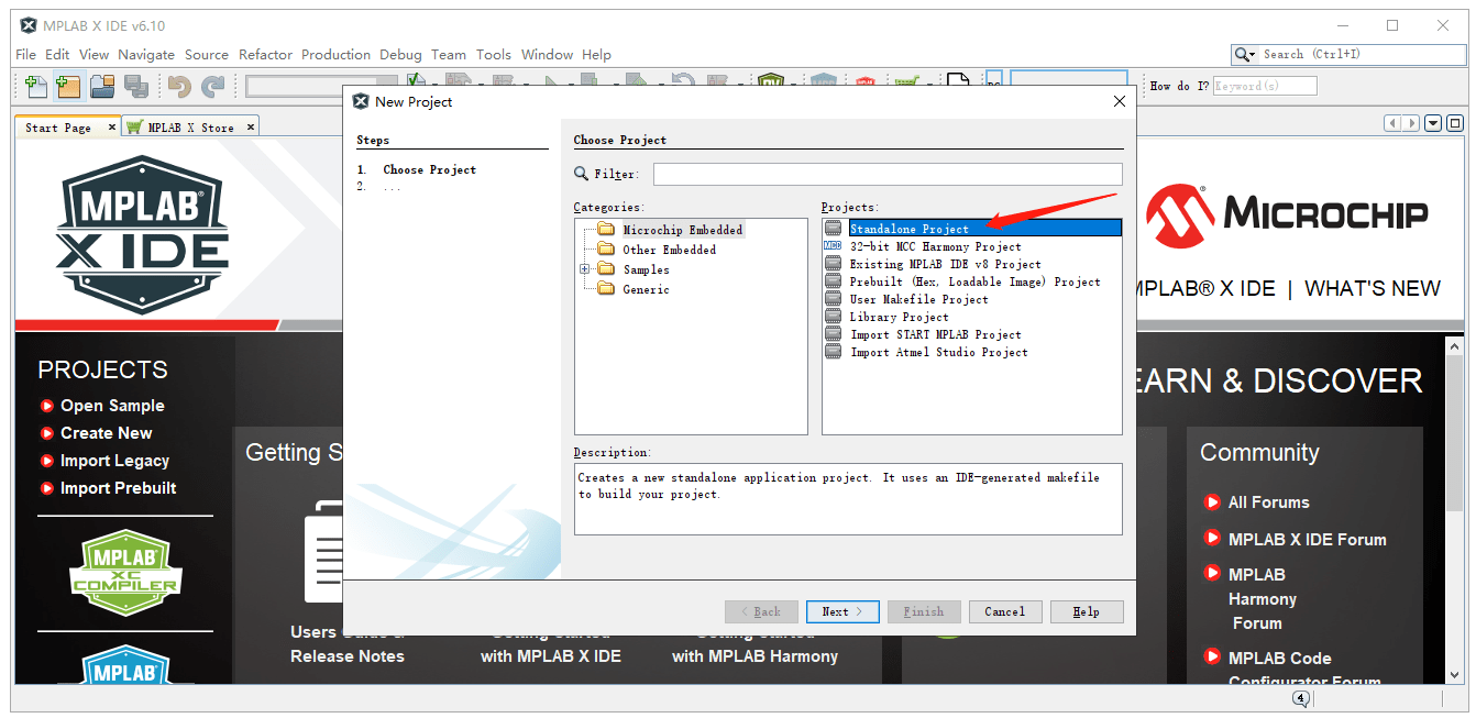
In this step, we choose “Microchip Embedded > Standalone Project”, it uses an IDE-generated makefile to build your project.
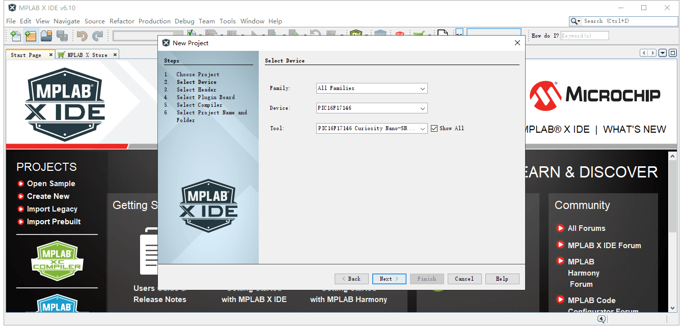
Next, select the device “PIC16F17146” and its’ tool.
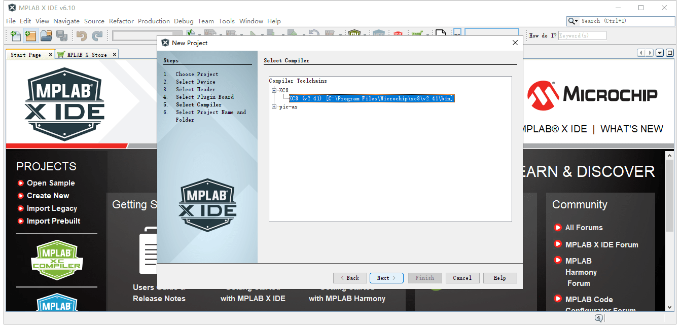
Select the compiler toolchains for your development board.
After finish the above steps, click the “MCC” buttom to configure the program code.

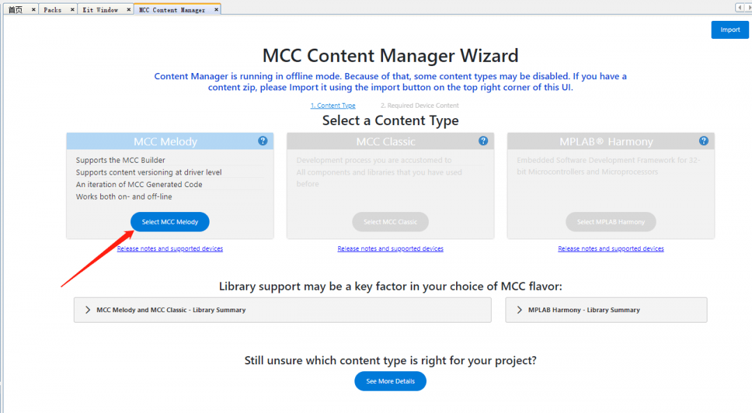
Select a content type in “MCC Content Manager Wizard” for your project, if you are not sure which to choose, please see the offical details.
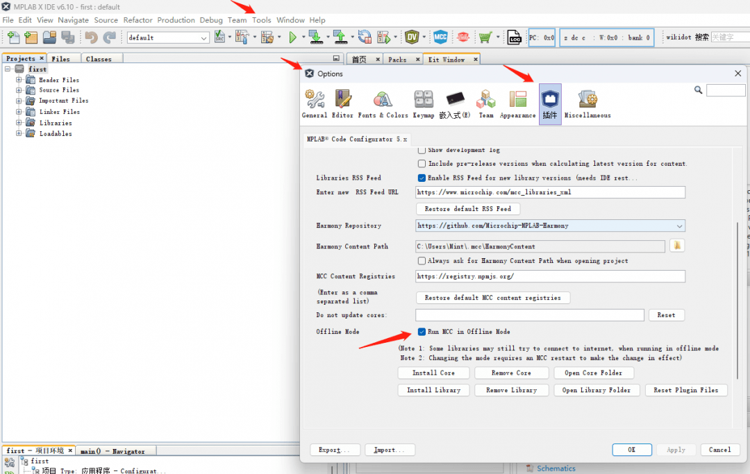
In order to ensure the quick start of MCC function, you can set it to offline mode.
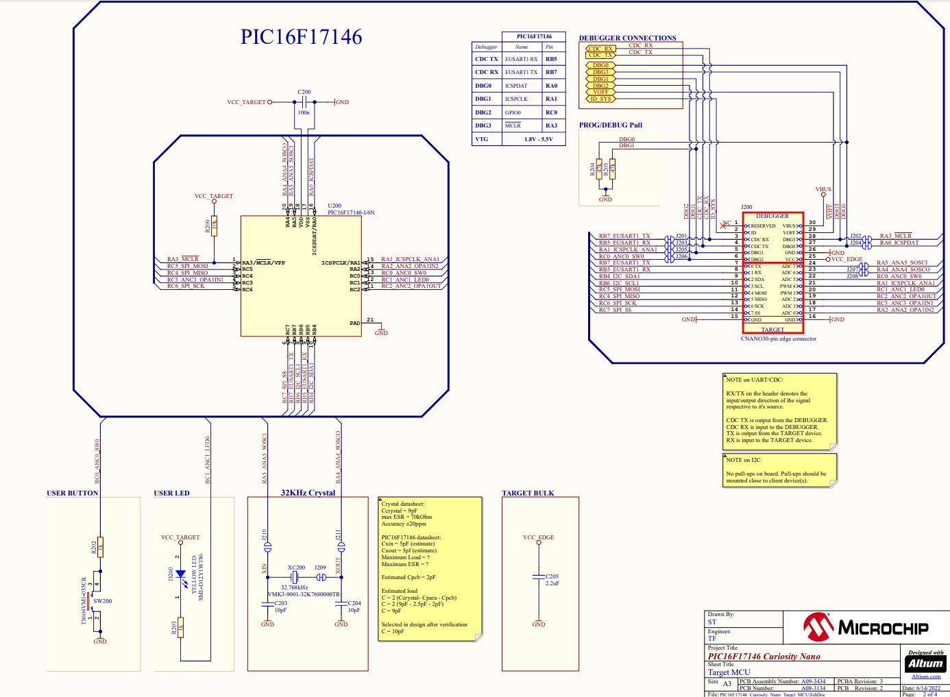
Before configuring the I/O, carefully read the PIC16F17146 Curiosity Nano Development Board schematic. From the schematic diagram, we can know that:
I/O lights up when RC1 outputs a low level; IO has no external pull-up resistor, so the on-chip pull-up can be configured, and the port triggers a low-level signal after being pressed.
The final configuration is as follows. This configuration will cause the LED to be turned on by default. If you want to turn off the LED by default, you can check the corresponding Start High, that is, the IO output is high when powered on.

If we don’t use the I/O interrupt function, the configuration ends here, click “Generate” to generate the code.

When writing code, we can use the code auto-completion function, the details are as follows:
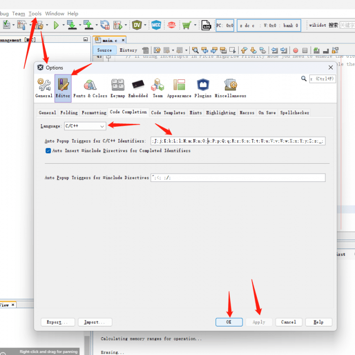
Auto Popup Triggers for C/C++ Identifiers:
.;->;.*;->*;::;new ;A;a;B;b;C;c;D;d;E;e;F;f;G;g;H;h;I;i;J;j;K;k;L;l;M;m;N;n;O;o;P;p;Q;q;R;r;S;s;T;t;U;u;V;v;W;w;X;x;Y;y;Z;z;_;
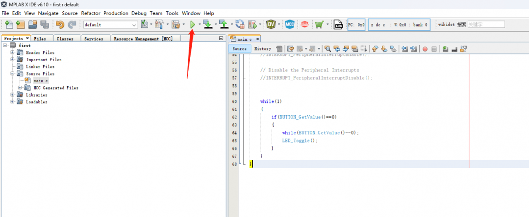
Write the code in the body of the loop as follows:
					    while(1)
    {
        if(BUTTON_GetValue()==0)
        {
            while(BUTTON_GetValue()==0);
            LED_Toggle();
        }
    }
Click the Run button to compile and burn the LED program to the PIC16F17146 Curiosity Nano development board.
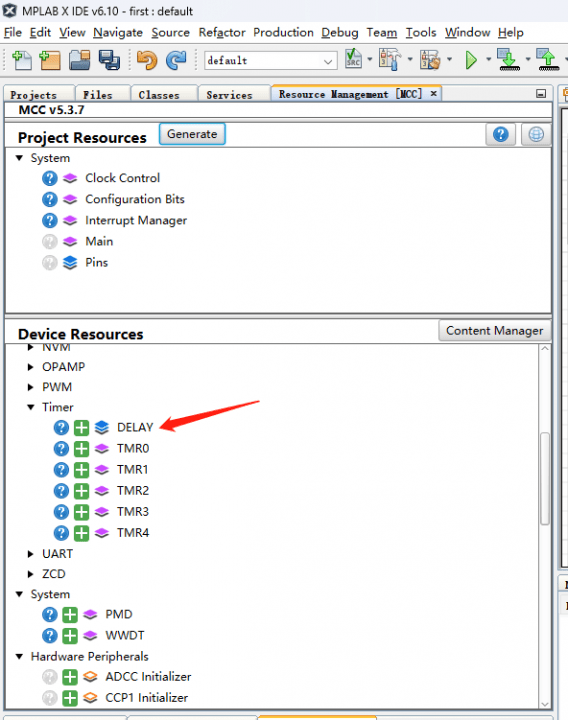
Next, go back to the MCC tab, add the delay function to the project, just click “Device Resources” > Timer > “DELAY”. And then, click the “Generate” buttom.
Now, we enter the letter “DE” in main.c and the delay function will appear.
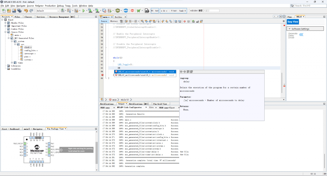
Our delay codes are as follows, one in microseconds and one in milliseconds:
					    while(1)
    {
        LED_Toggle();
        DELAY_milliseconds(500);
    }
Save and run this program, you can see that the LED on our development board starts blinking in 1 second cycle.
Reducing Power Consumption with PIC16F17146 Series
Many of today’s embedded designs involve analog systems, whether they include sensors, amplifiers, data converters, or any other analog modules. These designs are often battery-powered for the convenience of consumers in everyday electronics. However, battery life presents a challenge for designers, as analog signals need to be digitized and processed, which is not ideal for battery-powered applications. Below are several ways to reduce the power consumption:
Core Independent Peripherals (CIP)
With the PIC16F17146 series MCU, many analog designs can overcome power consumption challenges. PIC® and AVR® devices offer various Core Independent Peripherals (CIP). CIPs are dedicated hardware that can operate independently of the Central Processing Unit (CPU). Since there are numerous CIPs available on PIC and AVR devices, these can be used to offload other tasks from the CPU while handling sensor interfaces, waveform control, timing/measurement, and more. As a result, the system can run in low-power modes, leading to an overall reduction in design power consumption.
Analog-to-Digital Converter with Computation (ADCC)
One of the analog peripherals that offer energy-saving opportunities is our Analog-to-Digital Converter with Computation (ADCC). The CPU has several power-saving modes available to reduce overall power consumption. One of the energy-saving features provided by the PIC16F17146 series MCU is the SLEEP mode, where most of the MCU is turned off, consuming less power, and reducing measurement noise during ADC conversion. ADCC has a special oscillator that allows hardware to operate in sleep mode. When a wakeup trigger is activated, the CPU resumes operation shortly thereafter.
Idle mode and Doze mode
Other power-saving modes offered by the PIC16F17146 series MCU include Idle mode and Doze mode. In Idle mode, the CPU stops all other operations while the peripherals are active, and in Doze mode, the CPU runs with a reduced instruction clock.
Peripheral Module Disable (PMD)
Peripheral Module Disable (PMD) is another feature on the MCU. Even when not enabled, unused peripheral devices consume a small amount of parasitic power. By enabling PMD, users can enable or disable any unused peripheral devices. By disabling these peripherals, the MCU operates at its lowest possible power state, reducing its total power consumption.
In embedded development, the PIC16F17146 series MCU, along with other Microchip 8-bit MCUs, provides users with numerous options to optimize embedded system power consumption. For more information and to explore how to achieve low-power implementation in your next design, be sure to check out MPLAB® Discover, which houses a wealth of projects, including many low-power applications.


