What is a 7-Segment Display?
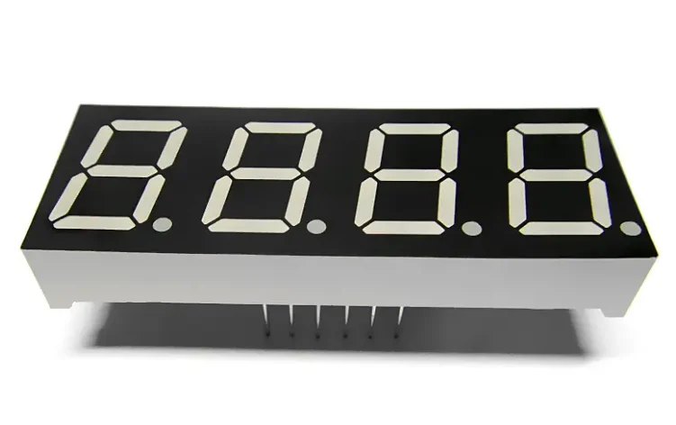
A 7-segment display is an electronic component made up of 7 individual LEDs arranged in a specific pattern to display digits (0-9) and some letters. These LEDs are named a, b, c, d, e, f, g, and the display typically includes an optional decimal point (dp).
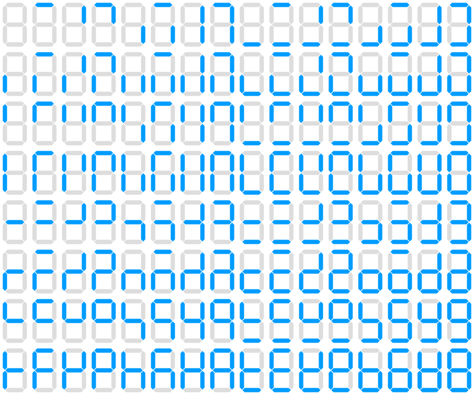

According to different arrangements and combinations, there are 128 variations ( arabic numerals and characters) for 7-segment display.
7-Segment Display Pinout
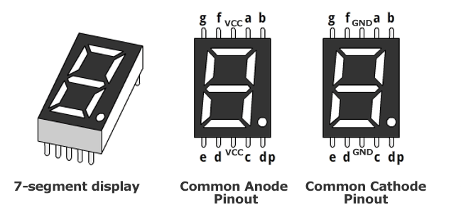
The pinout of a 7-segment display varies based on its type, which is mainly divided into two categories: common anode and common cathode.
Pinout Configuration
The following is an example pin assignment for a typical 7-segment display (note that actual pinouts may vary depending on the manufacturer and model):
Common Anode:
All anodes (positive) of the 7-segment display are connected together, and when a cathode is pulled low, the corresponding LED will light up.
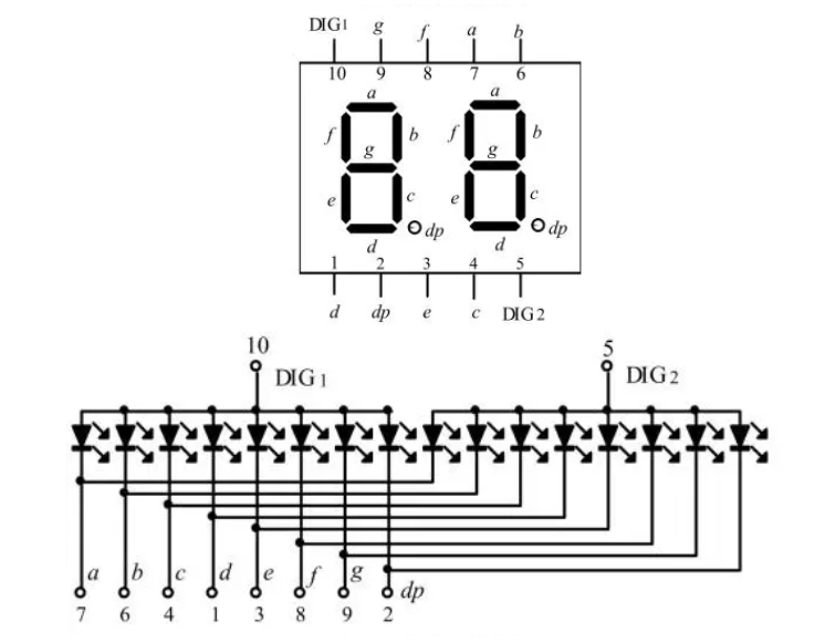
- g, f, a, b, e, d, c, dp: These are the segment pins, corresponding to the seven segments and the decimal point, respectively.
- COM: The common anode pin, connected to VCC.
Common Cathode:
All cathodes (negative) of the 7-segment display are connected together, and when an anode (positive) is pulled high, the corresponding LED will light up.
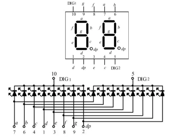
Similarly, the segment pins (g, f, a, b, e, d, c, dp) correspond to the segments and decimal point, but the common cathode pin (COM) is connected to GND.
Wiring the 7-Segment Display
To operate a 7-segment display, the individual segments (a, b, c, d, e, f, g, dp) need to be connected to specific output pins on a microcontroller. For example, for a common cathode 7-segment display, the negative end of each segment is connected to a common ground pin, while the positive end of each segment is connected to a different output pin on the microcontroller.
Basic Wiring Setup
- 7-segment display has 8 pins (7 for the segments and 1 for the decimal point).
- Each pin corresponding to a segment (a to g) is connected to the microcontroller.
- For the common cathode configuration, connect the common cathode pin to the ground.
Example Connection to Arduino
When interfacing a 7-segment display with an Arduino, the segment pins are typically connected to different digital pins on the Arduino board. For example, in a common anode configuration, the segment pins might be connected as follows:
- a – Arduino Pin 7
- b – Arduino Pin 8
- c – Arduino Pin 4
- d – Arduino Pin 3
- e – Arduino Pin 2
- f – Arduino Pin 6
- g – Arduino Pin 5
- COM – Arduino Pin 9 (connected to VCC)
In this configuration, to illuminate a specific segment, the corresponding Arduino pin is set to LOW, while the common anode pin remains HIGH.
How to Control a 7-Segment Display
The key to controlling a 7-segment display is to provide the correct voltage to the individual segments to form the desired number or symbol.
Displaying Numbers
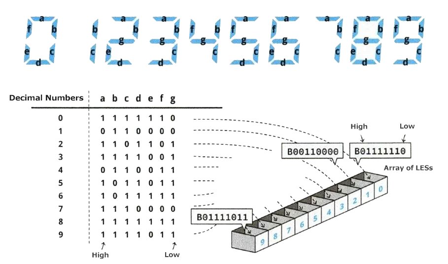
To display a number, the microcontroller needs to turn on the appropriate segments. For example:
- To display 0, segments a, b, c, d, e, and f should be illuminated, while segment g remains off.
Required Components
Similar to an LED matrix, this project will require a considerable amount of wiring and resistors. Since each LED needs its own resistor to prevent burnout, please ensure you have enough resistors prepared. For the entire project, you will need the following components:
- Arduino Uno
- Arduino IDE
- Seven-segment display
- Electrical wires
- 8x 220-ohm resistors
- Breadboard
- USB cable
Example Code for Displaying Numbers
					int pin_a = 7, pin_b= 6, pin_c = 5, pin_d = 10, pin_e = 11, pin_f = 8, pin_g = 9, pin_p = 4;

// Segment data for digits 0-9
int numTable[10][8] = {
  {1, 1, 1, 1, 1, 1, 0, 0}, // 0
  {0, 1, 1, 0, 0, 0, 0, 0}, // 1
  {1, 1, 0, 1, 1, 0, 1, 0}, // 2
  {1, 1, 1, 1, 0, 0, 1, 0}, // 3
  {0, 1, 1, 0, 0, 1, 1, 0}, // 4
  {1, 0, 1, 1, 0, 1, 1, 0}, // 5
  {1, 0, 1, 1, 1, 1, 1, 0}, // 6
  {1, 1, 1, 0, 0, 0, 0, 0}, // 7
  {1, 1, 1, 1, 1, 1, 1, 0}, // 8
  {1, 1, 1, 1, 0, 1, 1, 0}, // 9
};

void setup(){
  for (int i = 4; i <= 11; i++){
    pinMode(i, OUTPUT);
  }
}

void loop(){
  for (int i = 0; i < 10; i++){
    digitalWrite(pin_a, numTable[i][0]);
    digitalWrite(pin_b, numTable[i][1]);
    digitalWrite(pin_c, numTable[i][2]);
    digitalWrite(pin_d, numTable[i][3]);
    digitalWrite(pin_e, numTable[i][4]);
    digitalWrite(pin_f, numTable[i][5]);
    digitalWrite(pin_g, numTable[i][6]);
    digitalWrite(pin_p, numTable[i][7]);
    delay(1000);
  }
}
In this example, the numTable array holds the data required to turn on the appropriate segments for each digit.
Multi-digits 7-Segment Display Projects
For multi-digit displays, the simplest way to control multiple 7-segment displays is through multiplexing, another way is Arduino library.
Multiplexing Technique
With multiplexing, multiple displays share the same set of control pins, and each display is turned on sequentially. This is done so fast that the human eye perceives all the digits as lit at the same time.
Example Code for Multiplexing 7-Segment Displays
					const int digitPins[3] = {2, 3, 4}; // Digit selection pins
const int segmentPins[8] = {6, 7, 8, 9, 10, 11, 12, 13}; // Segment pins
int numTable[10][8] = { {0, 0, 0, 0, 0, 0, 1, 1}, {1, 0, 0, 1, 1, 1, 1, 1}, ... };

void setup(){
  for (int i = 2; i <= 4; i++) {
    pinMode(i, OUTPUT);
    digitalWrite(i, LOW);
  }
  for (int i = 6; i <= 13; i++) {
    pinMode(i, OUTPUT);
    digitalWrite(i, HIGH);
  }
}

void loop(){
  for (int i = 0; i < 10; i++){
    for (int j = 0; j < 3; j++) {
      showdigit(i, j);
    }
    delay(500);
  }
}

void showdigit(int num, int digit){
  digitalWrite(digitPins[digit], HIGH);
  for (int i = 0; i < 8; i++) {
    digitalWrite(segmentPins[i], numTable[num][i]);
  }
  delay(500);
  digitalWrite(digitPins[digit], LOW);
}
Using Libraries to Control 7-Segment Displays
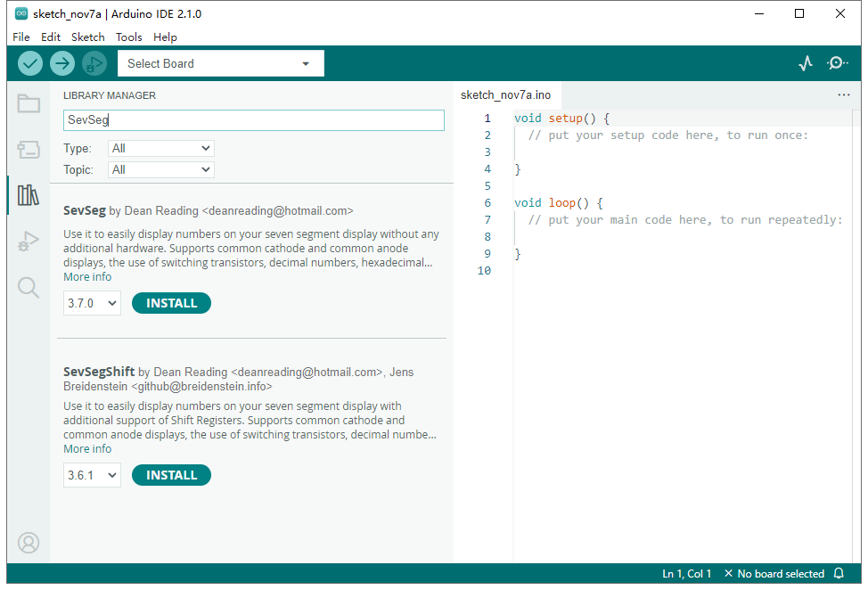
For convenience, libraries like SevSeg are available to simplify the control of 7-segment displays. This library is useful for controlling multi-digit displays, as it abstracts much of the complex wiring and control logic.
We can Search an install the SevSeg by the Arduino menu: Tools >> Manage Libraries.
Example Code Using the SevSeg Library
					#include "SevSeg.h"
SevSeg sevseg;

void setup() {
  sevseg.begin(COMMON_CATHODE, 3, digitPins, segmentPins);
}

void loop() {
  int readValue = analogRead(A0);
  int showValue = map(readValue, 0, 1023, 0, 999);
  sevseg.setNumber(showValue, 3);
  sevseg.refreshDisplay();
}
Applications of 7-Segment Displays
Due to its simplicity, ease of use, and low cost, the 7-segment display is widely used in various applications, such as:
- Electronic clocks: displaying time and date;
- Calculators: showing calculation results;
- Home appliances: display panels for products like microwaves, air conditioners, and washing machines;
- Car dashboards: displaying information such as speed and mileage;
- Industrial equipment: displaying readings from devices like temperature controllers and pressure gauges;
- Laboratory instruments: displaying experimental data and results;
- Consumer electronics: volume control display on audio equipment.
Conclusion
7-segment displays are versatile components that allow for the simple display of numeric data. Understanding their wiring, control methods, and applications can greatly enhance the functionality of your projects, from simple clocks to complex displays. Whether you’re using multiplexing, libraries, or shift registers, there are many ways to control 7-segment displays effectively, each suited to different project requirements.

