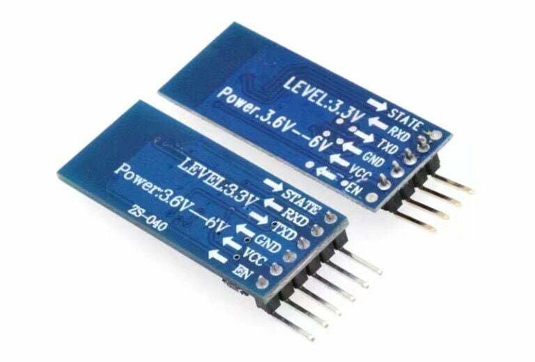
Introduce to HC-05 Bluetooth Module
HC-05 Bluetooth Module is a low power, wireless module used for wireless communication between two devices. It operates in the 2.4GHz ISM band and can be used to transfer data and control signals. It is widely used in robotics, home automation, and other consumer electronics. It has a simple serial port protocol and can be used to connect devices such as smartphones, tablets, and computers, to each other. It can also be used to connect devices to a home Wi-Fi network. An example would be using the HC-05 Bluetooth Module to connect a smartphone to a robotic arm, allowing the user to control the robotic arm with their smartphone.
Pin Configuration
The HC-05 Bluetooth module is a popular Bluetooth module which can add two-way wireless functionality to your projects. It has 6 pins: Key, Vcc, GND, TXD, RXD, State.
These pins are used to send data from one device to another. It also has an enable pin which allows toggling between command and data mode. The Key/EN pin should be high to operate in command mode and low to operate in data mode. Additionally, the Vcc and Ground pins are used to power the module, with +5V from the supply voltage. With these pins, HC-05 can be used for a variety of applications, such as data logging, consumer applications, and wireless robots
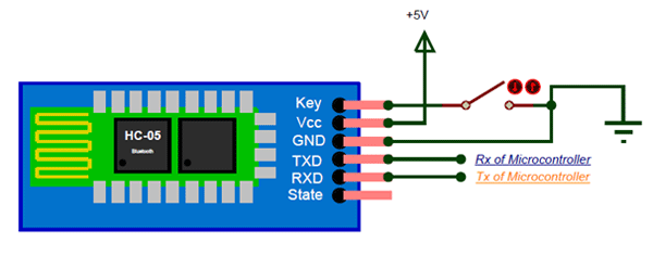
Circuit Diagram
To connect the HC-05 Bluetooth Module with Arduino, you need to have a circuit diagram. The circuit diagram of the HC-05 Bluetooth module and Arduino connection is quite simple and easy to understand. It consists of the HC-05 Bluetooth module, Arduino Uno Board, Breadboard, and Jump Wires.
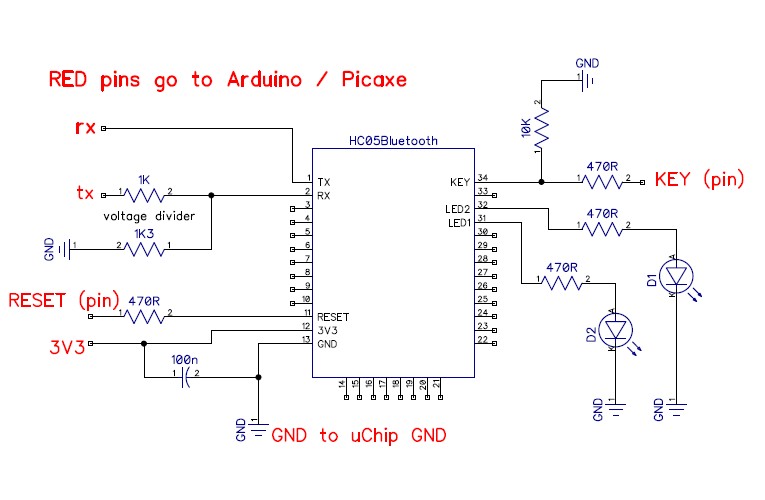
How to Program Bluetooth Module with Arduino?
In this post, we use Arduino UNO board to program HC-05 bluetooth module. Generally, there’re two necessary steps:
- Setting AT Mode on Bluetooth Module
- Programming and Degbugging
Setting AT Mode on HC-05 Bluetooth Module
The purpose of AT mode is to change the original parameters of HC-05 Bluetooth module. The basic parameters mainly include: Bluetooth name, mode and matching password, etc. Of course, there’re two ways to set up the AT Mode on the Bluetooth module:
- Using USB-TTL and serial port debugging software
- Using Arduino and Bluetooth module
Here we mainly introduce the second method.
1). Preparing the Materials:
- ArduinoUNO * 1
- HC-05 Bluetooth serial port module *1
- Mini LED light *1
- Dupont line *4
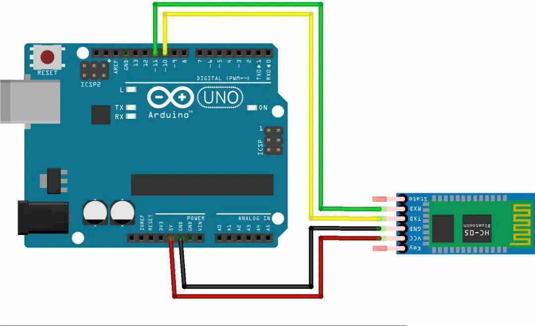
2). Connecting the Bluetooth Module with Arduino UNO:
To set the AT mode on bluetooth module, you should connect the wirings correctly to Arduino UNO board:
- Arduino 5V – VCC
- Arduino GND – GND
- Arduino Pin10 – TXD
- Arduino Pin11 – RXD
Remember to check the circuit connecting before power on, and avoid short circuit of the Pins.
3). Writing Arduino UNO Code for Bluetooth Module:
Next, we need to write a program code for HC-05 bluetooth module on Arduino IDE. This program allows us to set up the Bluetooth module through the serial monitor on the Arduino IDE. The code is as follow:
					#include <SoftwareSerial.h>

// Pin10-RX,connectting the TXD of HC05
// Pin11-TX,connectting the RXD of HC05

SoftwareSerial BT(10, 11);
char val;
void setup() {
  Serial.begin(38400);
  Serial.println("BT is ready!");

  // HC-05 default,38400

  BT.begin(38400);
}
void loop() {
  if (Serial.available()) {
    val = Serial.read();
    BT.print(val);
  }
  if (BT.available()) {
    val = BT.read();
    Serial.print(val);
  }
}
4). Debugging Code with the Arduino IDE Serial Monitor:
First, power off the Arduino UNO, then press and hold the black button on the Bluetooth module, and then power on the Arduino.
If the indicator light of the Bluetooth module flashes at a frequency of 2 seconds, it means that the Bluetooth module has entered the AT mode correctly.
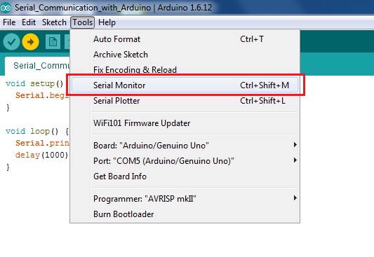
Open the serial monitor of the Arduino IDE and select the correct port. Set the output format to Both: NL & CR and the baud rate to 38400, and you can see the message BT is ready! displayed on the serial monitor.
Then, input AT, if everything is normal, the serial monitor will display OK.
5). Setting AT Commands for Bluetooth Module:
Once the bluetooth module has entered the AT mode correctly, we can add AT commands to it. The common AT commands are as follows:
					AT                  // check if the module is responding
AT+NAME             // set or get the name of the device
AT+ADDR             // get the Bluetooth address of the module
AT+ROLE             // set or get the role of the module
AT+PSWD             // set or get the password of the device
AT+UART             // set or get the UART interface settings
AT+RESET            // reset the module
Under normal circumstances, after the command is sent, it will return OK. If no information is returned, please check whether the wiring is correct and whether the Bluetooth module has entered AT mode.
After setting the AT command, restart the power. At this time, the indicator light of the Bluetooth module will flash quickly, which indicates that the Bluetooth module has entered the normal working mode.
Programming and Degbugging
After we have completed the AT setup of the Bluetooth module, we can start programming experiments on it. In this experiment, we will make a program that allows it to control the effect of the LED switch light on the Arduino UNO board through the mobile phone.
1). Arduino Circuit Designning:
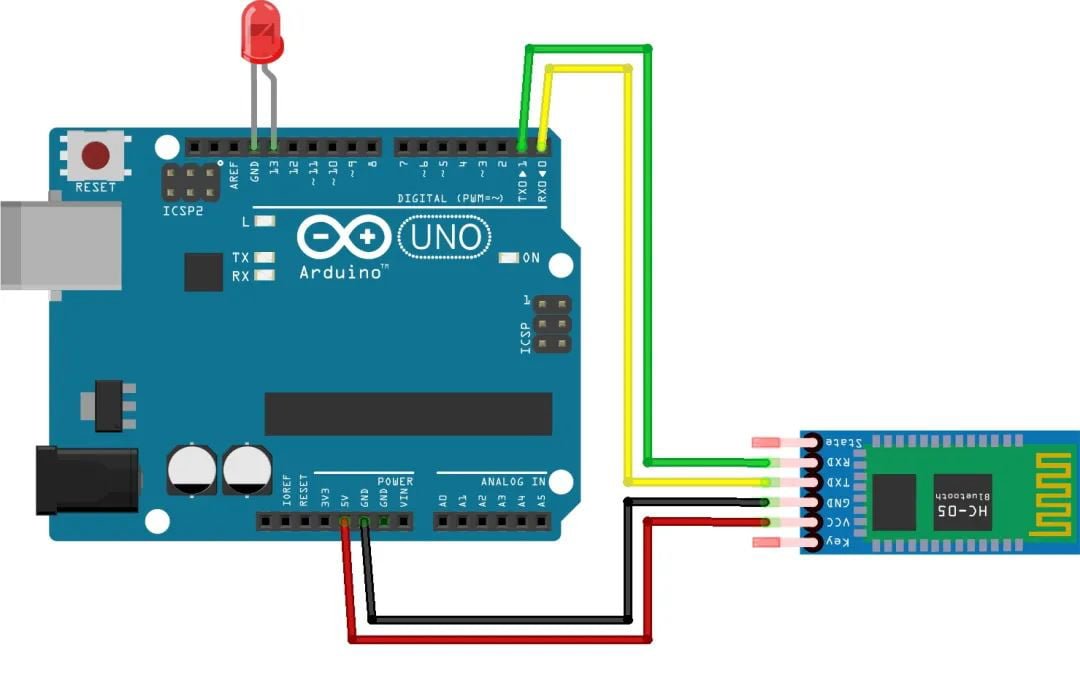
The circuit design here is relatively simple, mainly in two parts:
- Arduino and HC05 module connection
- Arduino and LED connection
There are two points to note here, the TXD on the Arduino should be connected to the RXD terminal on the HC05 module, and the RXD on the Arduino should be connected to the TXD on the HC05 module. In the figure below, my LED is directly connected to Pin13 of Arduino. But actually, you should consider whether a series resistor is needed according to the design of the LED light.
2). Adding Program Code to Arduino UNO Board:
The led blink code is as follow:
					void setup()

{
  // Set the baud rate to 38400

  Serial.begin(38400);
  pinMode(13, OUTPUT);
}
void loop()
{
  while(Serial.available())
  {
    char c=Serial.read();
      if(c=='1')
      {
        Serial.println("BT is ready!");

        // Return to the phone debugging program

        Serial.write("Serial--13--high");
        digitalWrite(13, HIGH);
      }
     if(c=='2')
     {
       Serial.write("Serial--13--low");
       digitalWrite(13, LOW);
     }
  }
}
3). Debugging the program on Mobile:
Installing the Bluetooth serial port module debugging software:
The Bluetooth serial port module is based on the SPP protocol (Serial PortProfile), a device that can create a serial port between Bluetooth devices for data transmission, and is widely used in electronic devices with Bluetooth functions. There are different Bluetooth serial port module debugging software on the Android side and the IOS side.
Degbugging the LED Blink Program:
After the software is downloaded and installed, we first open the Bluetooth settings of the mobile phone, search and connect with the Bluetooth module. Then open the Bluetooth serial port debugging software, let it connect to the Bluetooth module. Now we can enter the following debugging commands in the software and see different effects:
- “1” – the LED light is on, return Serial–13–high in the debug software.
- “2” – LED is off, return to Serial–13–low in the debug software.
Conclusion
In this article, you should be able to learn the basics knowledges and important steps of programming the HC05 Bluetooth module in Arduino.

