In the world of microcontrollers and electronics, there are many different types. One of the most popular microcontroller types is the AVR family. These microcontrollers can be used in a variety of projects or products, as they have many uses and functions.
If you want to get started with an Arduino project but aren’t sure how to program the AVR microcontroller with Arduino — don’t worry! In this blog post, we will cover all of your options!
What is AVR microcontroller?
An AVR microcontroller is a microcontroller that uses the AVR instruction set. AVR is a modified Harvard architecture 8-bit RISC single chip microcontroller which was developed by Atmel in 1996. AVR microcontrollers are often used in Arduino boards and when programming for Arduino boards, you will use the AVR microcontroller.

AVR microcontroller full form
The AVR microcontroller’s full form is Atmel AVR. It’s a type of microcontroller that was originally designed for embedded devices such as cars, cell phones, appliances, home monitoring systems and so much more! AVR microcontrollers are often used in Arduino boards and when programming for Arduino boards, you will use the AVR microcontroller.
AVR microcontroller features
– Low power – One of the best features of AVR microcontrollers is their low power usage. Depending on what you’re doing with the device, it can range from negligible to a couple of watts.
– Wide temperature range – While temperature can affect the speed of the device, AVR microcontrollers can withstand temperatures ranging from -40 degrees Celsius to 85 degrees Celsius.
– 8-bit architecture – Another feature of AVR microcontrollers is their 8-bit architecture. This allows your device to have more memory and more processing power.
– Programmer-friendly – Last but certainly not least, AVR microcontrollers are programmer-friendly. This makes them a great choice for beginners and hobbyists who want to create their projects.
AVR microcontroller architecture
The AVR architecture is based on a reduced instruction set computer (RISC) architecture. RISC architectures make the programming process much simpler and more efficient, which is one of the reasons AVR became so popular.
– Instruction set – The architecture’s instruction set is also reduced. While this may sound like it would make programming harder, it makes it easier because fewer instructions mean less complex instructions.
– 8-bit data path – The 8-bit architecture also means that it has a 8-bit data path, which means it can process more data at a time.
– Program memory – Program memory is where all of your programs are stored. It’s like a hard drive for your device.
– Data memory – Data memory is where your data is stored. For example, if you want to store a number in the device, it’s stored in data memory.
AVR microcontroller pin diagram
There are different types of AVR microcontrollers and the pin diagram will vary depending on the type. However, there are a few pin diagrams that are common in many types of AVR microcontrollers such as ATmega328P.

ATmega328P Pin Configuration
– RESET – RESET is a line that triggers when your device is reset. This can interfere with your program if the two are connected.
– GND – GND stands for ground. This is the connection your device will use to complete the circuit.
– VCC – VCC is the voltage used to power your device.
– RX – RX is an input pin that receives data from another device.
– TX – TX is an output pin that sends data to another device.
AVR microcontroller block diagram
The AVR microcontroller block diagram is the diagram that shows all of the internal parts of the microcontroller. Different models will have different parts, but each model is generally the same in terms of functionality.
– Program memory – Program memory is where your program is stored. This is like a hard drive for the device.
– Data memory – Data memory is where your data is stored.
– Program counter – The program counter keeps track of where you are in your program.
– Instruction register – The instruction register holds the next instruction that will be executed.
– ALU – The ALU stands for an arithmetic logic unit. This performs all of the mathematical operations in your program.
– Register file – The register file is a collection of the ALU’s registers. – Timer/counter – The timer/counter is used to measure time or count several events.
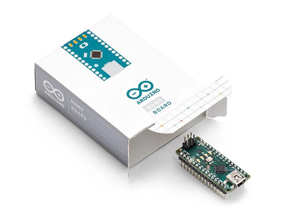
What is Arduino
Arduino is an open-source platform that makes it easy for people with little to no programming experience to design and create electronic projects. Arduino boards are capable of controlling a variety of lights, sensors, and other devices. Arduino boards use specific software to program them. If you want to program the AVR microcontroller with Arduino, you need to use a board specifically designed for it.
AVR microcontroller programming with Arduino
If you want to program the AVR microcontroller with Arduino, you will need to use an Arduino board designed for AVR microcontrollers. These boards are specifically designed to handle the programming of the AVR microcontroller. Programming the AVR microcontroller with Arduino is as easy as uploading a program to the board. Once you’ve uploaded the program, you need to reset the Arduino board and then unplug the power source. When you plug the power source back in, the AVR microcontroller with Arduino will be programmed.
1. Configure programmer-Arduino
First, you have to configure “programmer-Arduino” (the Arduino you have configured as a programmer) as ISP. By default, sketches (code) are available in Example Code in the Arduino IDE’s File menu. The Arduino ISP sketch passes the required instructions to the Programmer-Arduino to set it up in programming mode.

2. Connected LED to Arduino
As a second step, the status of the Programmer-Arduino can be monitored using the connected LEDs as shown. The Arduino ISP code is pre-programmed for this functionality.

LED Notes:
Pin 7 = programming (lights up when programming)
Pin 8 = Error (lights on when programming error)
Pin 9 = Normal (stays on once the programmer is powered up)
Once the Programmer-Arduino is configured, the connection between the Programmer-Arduino and the Arduino target is established. The pin configuration needs to be done exactly as described in the Arduino ISP code.
3. Configure SPI communication
The Arduino ISP communicates using the Serial Peripheral Interface (SPI) protocol to program the AVR microcontroller. SPI communication uses 4 logic signals: MOSI, MISO, SCLK and SS. Apart from I2C, SPI is one of the most commonly used communication modes for MCUs. SPI follows a master-slave architecture, which means that a master device can communicate with multiple slave devices using the same data pins, and the target slave device is selected using the slave select line.
If there is a memory card, select is used to select a specific chip among multiple chips. However, when you are using Arduino as a programming tool, the slave select signal is only used to reset the microcontroller. Reset the microcontroller in a state of accepting commands from the programmer’s Arduino.
On Programmer-Arduino, pins 10, 11, 12 and 13 are used as data pins. The configuration is as follows:
pin 10 = reset
Pin 11 = MOSI
Pin 12 = MISO
Pin 13 = SCK
4. configure ICSP header pins
In-Circuit Serial Programming (ICSP) is the ability to program a microcontroller without breaking the circuit. The ICSP header is available as 6 pins on the Arduino board. Connect pins 11, 12 and 13 of the target Arduino to pins 11, 12 and 13 of the programmer Arduino. Note that pin 10 of the programmer Arduino should be connected to the reset pin of the target Arduino. Alternatively, the ICSP header pins can be used for SPI communication.

5. Configure Arduino as ISP
After connecting everything above, you need to define that you are using Programmer mode on the host PC. Go to Tools in the menu and select “Arduino as ISP” in the “Programmer” option.

6. Burn the Bootloader to the Arduino
Next, load the bootloader into the target Arduino’s memory and define the “fuse”. In Arduino-land, a fuse is a set of instructions used to define multiple functions in a microcontroller. For example, chip frequency and clock source are defined in fuses. Microcontrollers are sensitive to operating voltages and may malfunction if the voltage levels are lower than specified. The minimum operating voltage is also defined within the fuse.

Precautions
#1. If the microcontroller or Arduino board can communicate with the Arduino IDE program, there are various advantages, such as being able to use the Arduino IDE’s serial monitor to check the results at runtime. (The Serial Monitor opens in a separate window, acting as a separate terminal for receiving and sending serial data.)
#2. If the bootloader is not loaded in the microcontroller, it will not be able to use the functions of the Arduino and will not be able to communicate with the Arduino IDE. The bootloader takes up part of the memory. In some cases, it is not necessary to use the Arduino IDE, so the bootloader does not need to be programmed. If the bootloader is not programmed, more memory can be freed up for the main program sketch. For example, in Arduino UNO, the total memory size is 32 KB, and 0.5 KB of memory is allocated for the bootloader. If the bootloader is not installed, the total available memory for the main program sketch is greater.
Summary
The AVR microcontroller is an easy-to-use and powerful chip that can be programmed for a wide range of applications. It’s a great chip for beginners who want to get into microcontrollers and electronics. The Arduino platform is a great way to get started with microcontrollers and is designed specifically with beginners in mind.