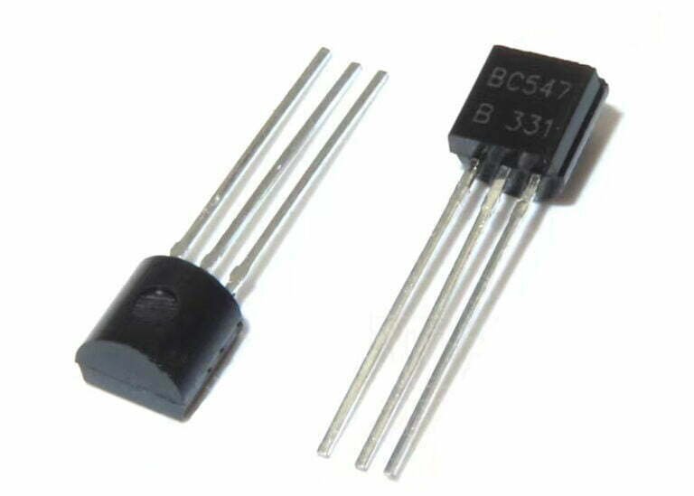
A semiconductor device such as a transistor is an electrically controlled switch, which consists of three terminals, such as i/p, o/p, and a control line, and is named emitter (E), collector (C) and base (B ), which work like switches and amplifiers to convert waves from audio to electronic.
Transistors are smaller, last longer, and can operate from low-voltage supplies. In modern electronic products, it is one of the basic electronic components used in various electrical and electronic systems, and its importance is self-evident. In this article, a brief introduction to the basics of the BC547 transistor.
Introduction to BC547 Transistor
BC547 is an NPN transistor where a small current at its base terminal will control a large current at both emitter and base terminals. The main function of this transistor is for amplification as well as switching purposes. The transistor has a maximum gain current of 800A.
Similar transistors such as BC548 and BC549. The BC547 transistor operates at a fixed DC voltage in a preferred region of its characteristics called bias. In addition, the series connection of this transistor can be divided into three groups according to the current gain, such as BC547A, BC547B and BC547C.
BC547 Pin Configuration
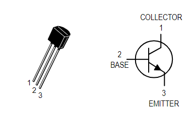
The BC547 transistor includes three pins, and its pin configuration is shown in the figure below:

- Pin1 (Collector): This pin is denoted by the symbol “C” and the current will flow through the collector terminal.
- Pin2 (Base): This pin controls the transistor bias.
- Pin3 (emitter): The current is output through the emitter.
If the BC547 transistor works as an amplifier, it works simultaneously in the active region to amplify voltage, current and power in various configurations. Then, three configurations are used in the amplifier circuit, including the following:
- Common emitter (CE) amplifiers.
- Common collector (CC) amplifiers.
- Common base (CB) amplifier.
Working Modes of BC547
The working state of the BC547 transistor includes the following two types:
- Forward bias.
- Reverse bias.
In forward bias mode, two terminals such as emitter and collector are connected to allow current to flow. Whereas in reverse bias mode it does not allow current to flow through it as it works as an open switch.
BC547 Specification
The specifications and characteristics of the BC547 transistor include the following:
- DC current gain (hFE) = 800A
- Continuous Ic (collector current) = 100mA
- VBE (emitter-base voltage) = 6V
- IB (base current) = 5mA
- The polarity of the triode is NPN
- Transition frequency is 300MHz
- Power consumption is 625mW
Application Circuit of BC547 Transistor
The diagram below illustrates the operation of an ON/OFF touch switch employing a BC547 transistor. When the circuit is powered on, it becomes active, and the relay remains in the off state. This is achieved by maintaining a high voltage at the base of the Q3 transistor through the R7 resistor, effectively keeping it turned off.

Upon opening switch S2, the Q4 transistor starts conducting, allowing the relay labeled as “L3” to latch. Consequently, the base terminal of the Q3 transistor is pulled to a low voltage level, causing the L2 LED to blink and indicate that power is now supplied. The Q4 transistor turns on due to the voltage across the collector terminal of transistor Q3, facilitated by the presence of the R8 resistor.
When switch S1 is momentarily pressed, the base of transistor Q3 is pulled to a high voltage level, resulting in the deactivation of L2. This occurs because the base of the Q4 transistor is pulled down through the R8 resistor, causing the relay L3 to turn off.
Precautions
Considerations for using the BC547 transistor include the following:
- To run a transistor in a circuit for a long time, it is very important not to add more than 100mA to the load.
- The voltage across the transistor should not exceed 45V DC.
- The base resistor should be used to provide the necessary current required for saturation.
- Keep the temperature from -65°C to +150°C.
- When connecting the circuit, be sure to check the three terminals of the transistor, otherwise it will reduce the performance and damage the circuit.
Application of BC547 Transistor
Applications of the BC547 transistor include the following:
- Used as substitutes and substitutes for various transistors.
- Current amplification
- Transistor Darlington pair
- LED driver, relay driver and other drivers.
- Amplifiers, such as audio, signal, etc.
- Quick switching
- PWM (Pulse Width Modulation)
In addition, these transistors are used to build various electrical and electronic circuits, examples of electronic applications include:
- Alarm circuit
- LED flash circuit
- Water level indicator
- Audio preamplifier circuit
- RF circuit
- Touch switch circuit
- Humidity alarm
- Street lamp circuit
- Single-channel based relay driver
- Volume indicator
BC547 Equivalent Transistor
The BC547 transistor belongs to the general-purpose NPN bipolar junction transistor (BJT) family. There are several equivalent transistors that can be used as alternatives to the BC547. Some of the common equivalent transistors include:
- 2N3904
- PN2222
- 2SC1815
- NTE123AP
- KSC945
- MPSA18
Please note that while these transistors are considered equivalents to the BC547, there might be slight variations in their electrical characteristics and specifications. It is always advisable to consult the datasheets of the specific transistors to ensure they meet the requirements of your circuit.
Conclusion
The above is the introduction to the relevant content of the BC547 transistor data sheet. It can be seen that it is an NPN BJT. A small amount of current in the base terminal of the BC547 transistor will control a large current in the collector and emitter terminals of the transistor, so these transistors are specially used for switching and amplification purposes, and the maximum gain of its current is 800A.


