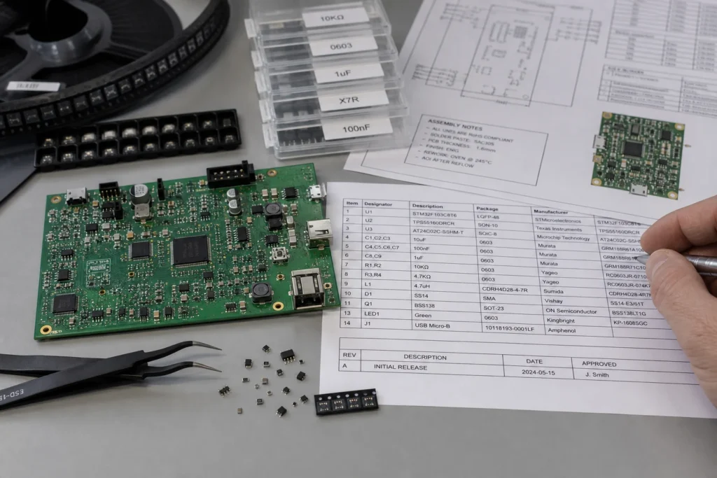
SMD and SMT are often treated as interchangeable, especially in casual conversation. That shortcut usually survives until the board leaves the engineer’s screen and reaches purchasing, assembly, or quality. At that point, the difference stops being academic. A component list, a feeder setup sheet, and a reflow process note are not talking about the same thing, so the language has to stay precise enough for the factory to act on it.
The simplest distinction is this: SMD means surface-mount device, while SMT means surface-mount technology. One names the part. The other names the method used to assemble that part onto the PCB. The reason this matters is that release-package errors usually start when the device term and the process term get mixed together in BOM notes, assembly drawings, or supplier communication.
SMD identifies the part, not the assembly process
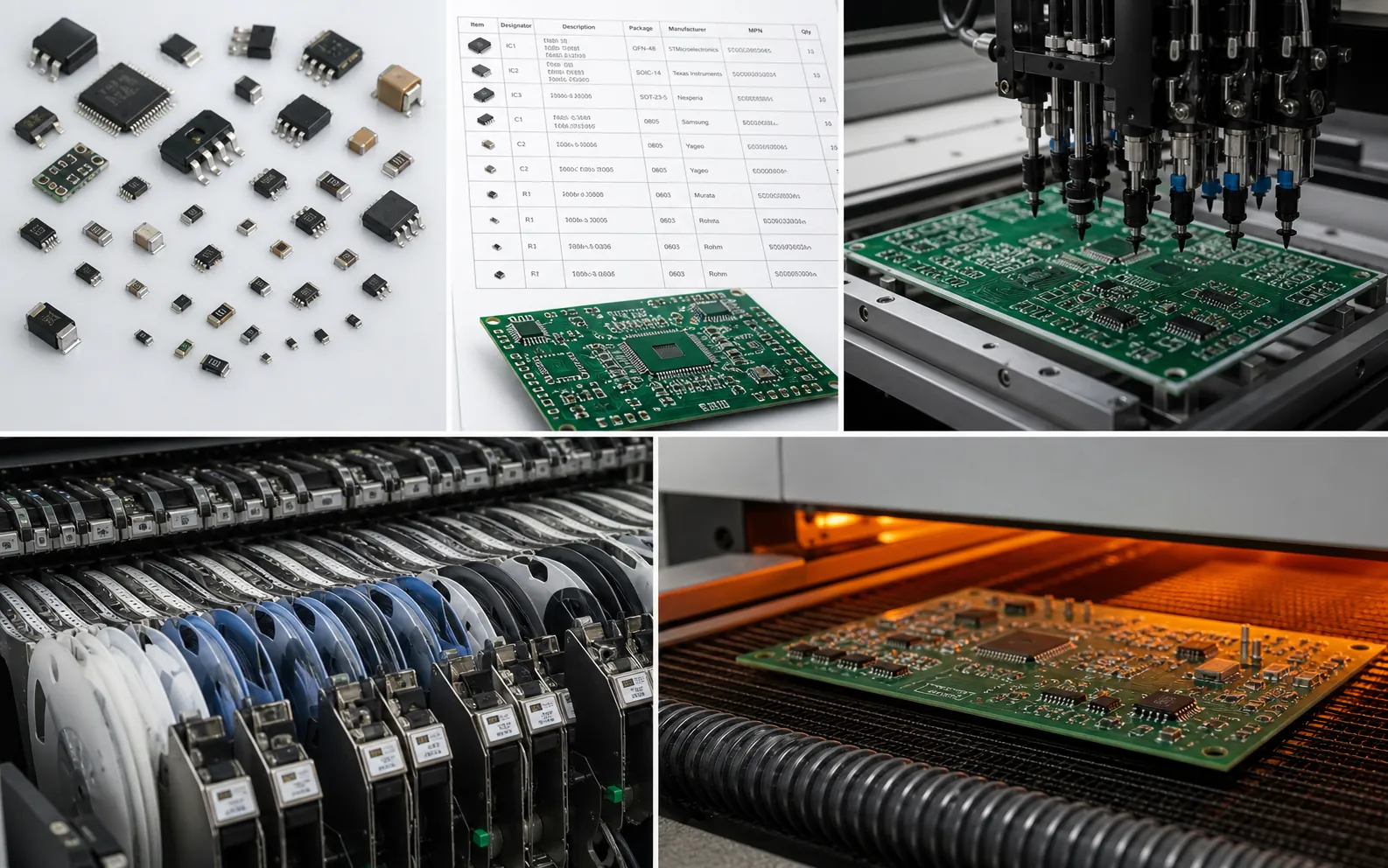
When engineers say SMD, they are talking about the physical device family: resistors, capacitors, ICs, LEDs, sensors, regulators, or connectors packaged for direct pad mounting. The term is useful when describing package style, feeder requirements, moisture sensitivity, polarity, or rework access. If someone asks whether a part is SMD, they are asking about the component itself and the footprint strategy that comes with it.
That is why documents such as the BOM, AVL, package library, and placement list tend to live closer to SMD language. A buyer may need the exact manufacturer package. A librarian may need the footprint and 3D body. A process engineer may need to know whether the device is leadless, fine pitch, bottom terminated, or mechanically vulnerable. Those are device questions, not technology questions.
SMT describes the manufacturing method wrapped around those devices
SMT is the process world around the parts: stencil printing, placement, reflow, AOI, X-ray where needed, and the control windows that keep those steps stable. If you are discussing line balance, paste deposition, nozzle choice, feeder setup, thermal profiling, or inspection access, you are in SMT language. ReversePCB’s guide on what SMT means in PCB assembly is a good reminder that the technology is larger than the part itself.
This difference may look obvious on paper, but teams still blur it in practice. A drawing note that says “confirm SMD process” is imprecise. Does it mean confirm the part package, the pick-and-place setup, or the reflow profile? A sourcing note that says “SMT component acceptable” is equally muddy. Precise terminology matters because unclear notes force the receiving team to guess what problem the author was actually trying to prevent.
Where the distinction matters most in real PCB documentation
The term boundary becomes most useful when a design package is being handed off. In the BOM, use device-oriented language: package, MPN, approved alternates, DNP markers, polarity, and moisture handling where relevant. In the assembly instruction, use process-oriented language: stencil thickness, paste exceptions, placement orientation checks, reflow constraints, selective hand-solder exceptions, or inspection notes. When those two layers are merged into one vague bucket, manufacturing questions multiply.
It also affects design review. A package may be electrically fine yet still create assembly trouble. That is why surface mount device package selection should be reviewed with the process team in mind. An 0201 resistor is an SMD choice. The tombstoning and feeder stability concerns it raises belong to SMT process planning. The terms are connected, but they are not interchangeable.
How confusion between SMD and SMT turns into avoidable build mistakes
One common failure is assuming that declaring a board “SMT” says enough about the parts. It does not. Two fully SMT boards can have completely different risk profiles depending on whether they use forgiving gull-wing packages or dense bottom-terminated devices. Another common failure is documenting device exceptions in process language, which leaves operators unsure whether a note refers to one reference designator or to a whole line setting.
Confusion also hurts procurement. If the purchasing team knows a board is SMT-based but does not have clean SMD package ownership, substitutions become dangerous. An alternate part may meet value and voltage requirements but arrive in a package that changes land pattern assumptions, stencil behavior, or inspection access. That is one reason strong SMT assembly process control starts with clean documentation, not just good machines.
When to say SMD and when to say SMT
Use SMD when the topic is the component package, footprint, part family, or device-level handling rule. Use SMT when the topic is the production method used to print, place, solder, and inspect those devices. If the sentence would still make sense after replacing the term with “component,” it is probably SMD territory. If it would still make sense after replacing the term with “assembly process,” it is probably SMT territory.
This sounds simple, but it is a useful test for release notes, supplier questions, and design reviews. Good terminology reduces back-and-forth, and less back-and-forth usually means fewer assumptions made on the factory floor.
Conclusion
SMD and SMT belong to the same manufacturing ecosystem, but they solve different language problems. SMD tells you what the part is. SMT tells you how the board is being built around that part. Keeping that distinction clean improves documentation quality, substitution control, and communication between design and assembly teams.
FAQ
Is SMD the same as SMT?
No. SMD means surface-mount device, which refers to the component. SMT means surface-mount technology, which refers to the assembly method used to mount and solder those components on the PCB.
Where should SMD be used in PCB documentation?
SMD is best used in device-oriented documents such as the BOM, package library, approved alternates list, footprint review notes, and any instruction that refers to the component body or package style.
Where should SMT be used in PCB documentation?
SMT belongs in process-oriented discussions such as stencil printing, placement setup, reflow profiling, AOI planning, and line-level assembly instructions.
Why does confusing SMD and SMT cause manufacturing problems?
It leads to vague notes, poor substitution control, and avoidable handoff errors. Teams can end up guessing whether a note refers to the component package or to the assembly process around it.