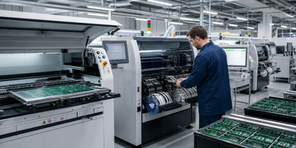
SMT assembly does not become stable at the oven. By the time the board reaches reflow, most of the outcome has already been shaped by land pattern choices, stencil design, paste control, part handling, and whether the placement program matches the physical reality of the board. Reflow can expose a weak process, but it rarely rescues one.
That matters because many discussions about surface-mount production jump straight to machine count or line speed. Real yields move earlier than that. The board succeeds when paste volume is repeatable, polarities are unambiguous, thermal mass differences were considered, and inspection can still see what needs to be judged after soldering. When those basics are loose, faster throughput only produces defects more efficiently.
What SMT Assembly Actually Includes
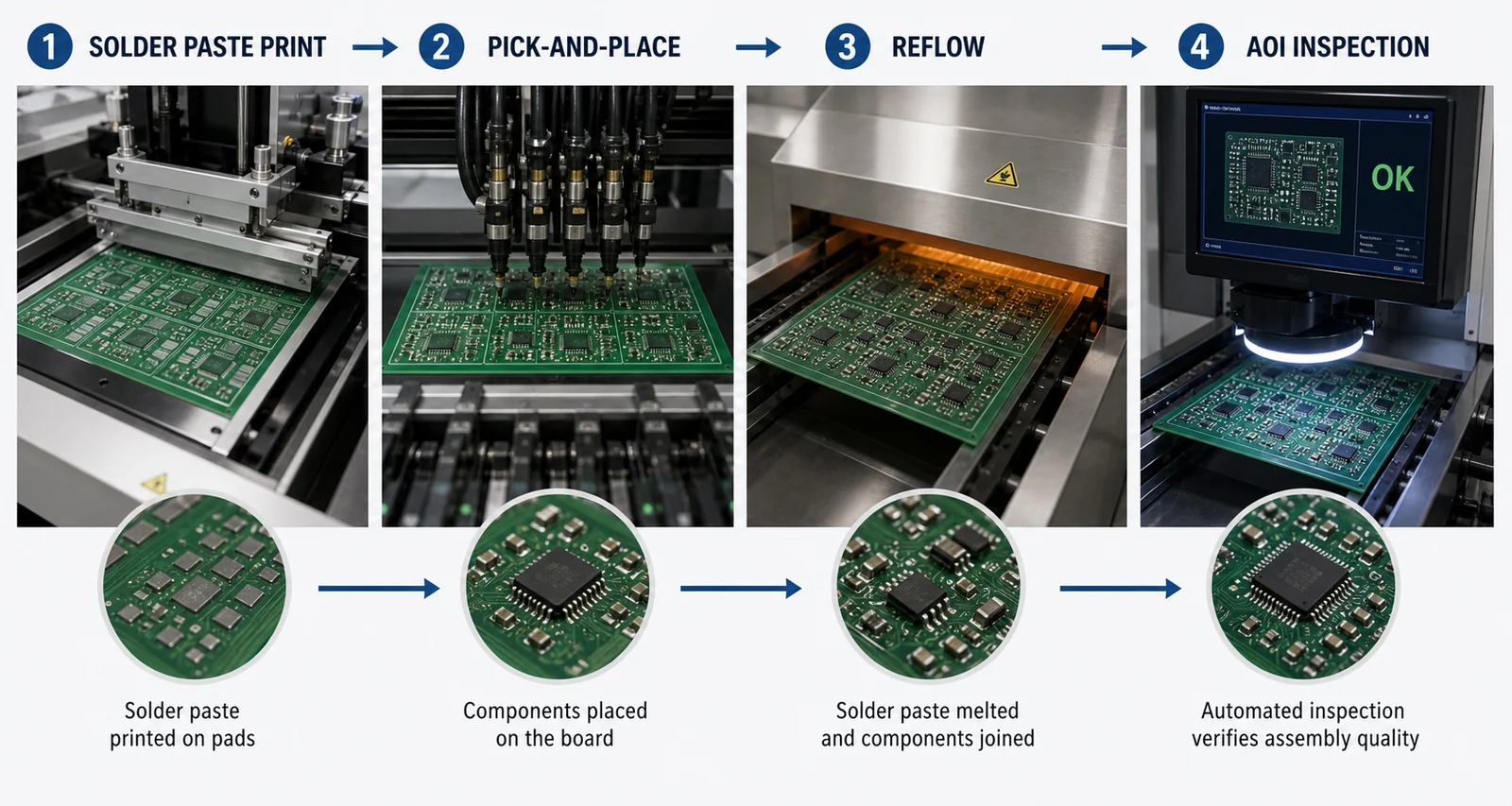
In a production context, SMT assembly is the controlled sequence that turns a bare board and a component reel set into a soldered, inspectable, testable PCBA. At a minimum, that usually includes solder paste printing, component placement, reflow, inspection, touch-up or rework when needed, and transfer into downstream test or mixed-technology operations.
That definition sounds straightforward, but every stage pushes on the next one. A design that ignores package spacing or rework access makes placement and inspection harder. Poor stencil aperture choices shift paste volume, which changes wetting balance, which changes tombstoning and voiding behavior, which changes how much manual repair the line absorbs later.
For readers who already know what SMT means in PCB assembly, the more useful question is what actually keeps an SMT line predictable when the board is not an easy textbook example.
Paste Printing Usually Decides Whether the Rest of the Line Has a Chance
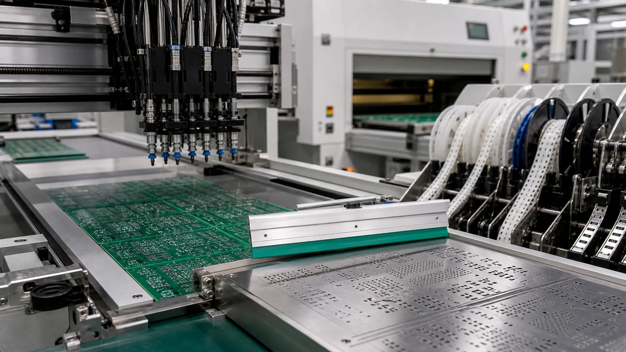
Most recurring SMT defects begin with solder paste, not with the pick-and-place head. If the print is inconsistent, the line can still look busy while joints become noisy, bridges increase, and small passives lose margin against tombstoning or opens.
Aperture design must reflect pad geometry, fine-pitch risk, and thermal pad behavior rather than blindly matching copper.
Stencil thickness affects both deposition volume and release reliability, especially when one board mixes tiny passives with larger power parts.
Board support matters on thin or irregular panels because print pressure changes deposit consistency.
Paste age and handling matter because slump, tack, and metal load stability change how parts sit before reflow.
This is why weak print control often shows up later as “reflow problems” that are not really oven problems at all. ReversePCB readers who have seen stencil decisions turn into yield loss already know that print quality has a longer shadow than most line dashboards admit.
Placement Accuracy Is More Than Hitting XY Coordinates
Pick-and-place accuracy matters, but so does everything that makes placement trustworthy. Feeders must present parts consistently, centroid data must reflect the real board origin and rotation conventions, and fragile packages must not be forced into tight spaces that leave no recovery margin after slight skew.
Three issues repeatedly create trouble in SMT assembly:
Rotation mismatches between CAD output, library origin choices, and machine expectations.
Package selection mistakes where a part can be placed, but not inspected or reworked comfortably after soldering.
Panelization compromises that let placement happen but make conveyors, rails, or support tooling less stable than planned.
That is where package choice becomes part of process engineering, not only electrical design. A dense component option can look attractive in the schematic library and still be the wrong answer if it forces inspection blind spots or expensive manual touch-up.
Reflow Should Confirm the Process Window, Not Define It
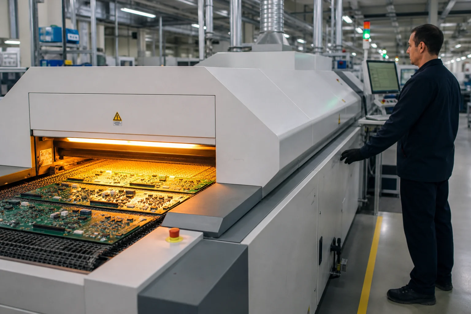
Reflow profile work still matters, but it is more effective when it is used to confirm a known process window rather than to compensate for unstable inputs. A good profile must account for board mass variation, component thermal inertia, soak behavior, peak exposure, and cooling rate. On mixed-density boards, that usually means balancing what the largest thermal pad needs against what the smallest passive can tolerate without movement or damage.
Common warning signs include solder joints that look acceptable on one area of the board but not another, voiding that tracks with thermal pad geometry, and repeated defects that disappear only when the line slows down enough to hide the real issue. Those are clues that the process window is narrow, not proof that the board is healthy.
Whether the line uses convection, vapor phase, or a profile tuned for special materials, the best result still starts with stable inputs before the board ever enters the oven.
Inspection and Rework Need to Be Designed In Early
SMT assembly gets expensive when the board can technically be soldered but cannot be judged or repaired efficiently. AOI needs contrast, access, and sensible part spacing. X-ray helps on hidden joints, but it is not a substitute for better land patterns or clearer process intent. Manual rework becomes slower and riskier when tall connectors crowd fine-pitch ICs or when a thermal pad pulls too much heat into a local area.
A practical assembly review should ask:
Can polarity and reference designator mapping be confirmed quickly?
Can likely defect locations be inspected with the tools the line actually uses?
Can a failed part be removed and replaced without damaging nearby pads or shields?
Will touch-up introduce more thermal stress than the joint is worth?
Boards that ignore those questions can still pass a pilot build and then become costly once defect escape, repair time, or technician variability starts to matter.
SMT Assembly Quality Is Built by Cross-Functional Discipline
Stable SMT assembly is rarely the result of one perfect machine. It comes from design, manufacturing engineering, purchasing, and test teams agreeing on the same assumptions before the first panel runs. The board library must tell the truth about the part. The BOM must reflect parts the process can actually support. The stencil and profile must match the physical board, not a generic template. Inspection must be possible on the real geometry, not only in a slide deck.
When those pieces line up, SMT assembly becomes much less mysterious. Yields improve because defects are prevented early, not because the line got better at cleaning them up later.
FAQ
What is SMT assembly in PCB manufacturing?
SMT assembly is the process of printing solder paste, placing surface-mount components, reflowing the board, inspecting the soldered result, and repairing or testing the assembly as needed. It is the production path that turns a bare PCB into a populated surface-mount assembly.
Why do SMT defects often start before reflow?
Because stencil design, paste condition, placement accuracy, and board support already determine how the solder joints will behave. Reflow exposes those conditions, but it usually does not create them from nothing.
What matters most in SMT assembly quality control?
Repeatable paste deposition, accurate component placement, a realistic reflow window, and inspection access that can confirm the joints that matter. Quality control works best when it is tied to process capability rather than only end-of-line repair.
How does PCB design affect SMT assembly yield?
Design choices affect spacing, thermal balance, inspection visibility, rework access, and stencil behavior. A board can be electrically correct and still assemble poorly if package selection and layout density ignore manufacturing constraints.