PIC Microcontroller: What It Is, Where It Fits, and What to Check Before You Design With One
A PIC microcontroller is a compact programmable chip from Microchip that combines a CPU, memory, and input/output peripherals in one package. Instead of building a control system from several separate ICs, a designer can use one microcontroller to read sensors, drive outputs, communicate with other devices, and run embedded firmware.

PIC devices have been around for decades, so they still show up in industrial controls, consumer products, hobby boards, maintenance replacements, and reverse-engineering work. Even if newer ARM-based parts dominate many new designs, PIC parts remain common in cost-sensitive products and in legacy equipment that needs service or redesign.
For hardware teams, the practical question is not just "what is a PIC microcontroller?" It is whether a PIC family matches the I/O count, voltage range, timing needs, firmware complexity, and lifecycle risk of the product you are building. That is where board design, part selection, and manufacturing details start to matter.
This guide explains what a PIC microcontroller is, how it works, where it is used, how it compares with other MCU options, and what to watch before you put one on a new or replacement printed circuit board.
What Is a PIC Microcontroller?
PIC stands for Peripheral Interface Controller, although in day-to-day engineering use people usually just say "PIC MCU" or "PIC microcontroller." A PIC device is a single-chip controller with a processor core, flash or program memory, RAM, timers, GPIO, and communication blocks such as UART, SPI, or I2C.
Different PIC families target different levels of complexity. Small 8-bit parts are often used for simple control jobs like relay timing, keypad scanning, LED control, or battery-powered housekeeping tasks. Higher-end PIC families can handle motor control, USB, analog sensing, safety features, and more demanding firmware.
One reason PIC parts remain relevant is that there is a large installed base. If a customer needs a failed control board copied, repaired, or updated, the original design may already depend on a PIC MCU. In those cases, redesigning around a different architecture can create unnecessary firmware and validation work.
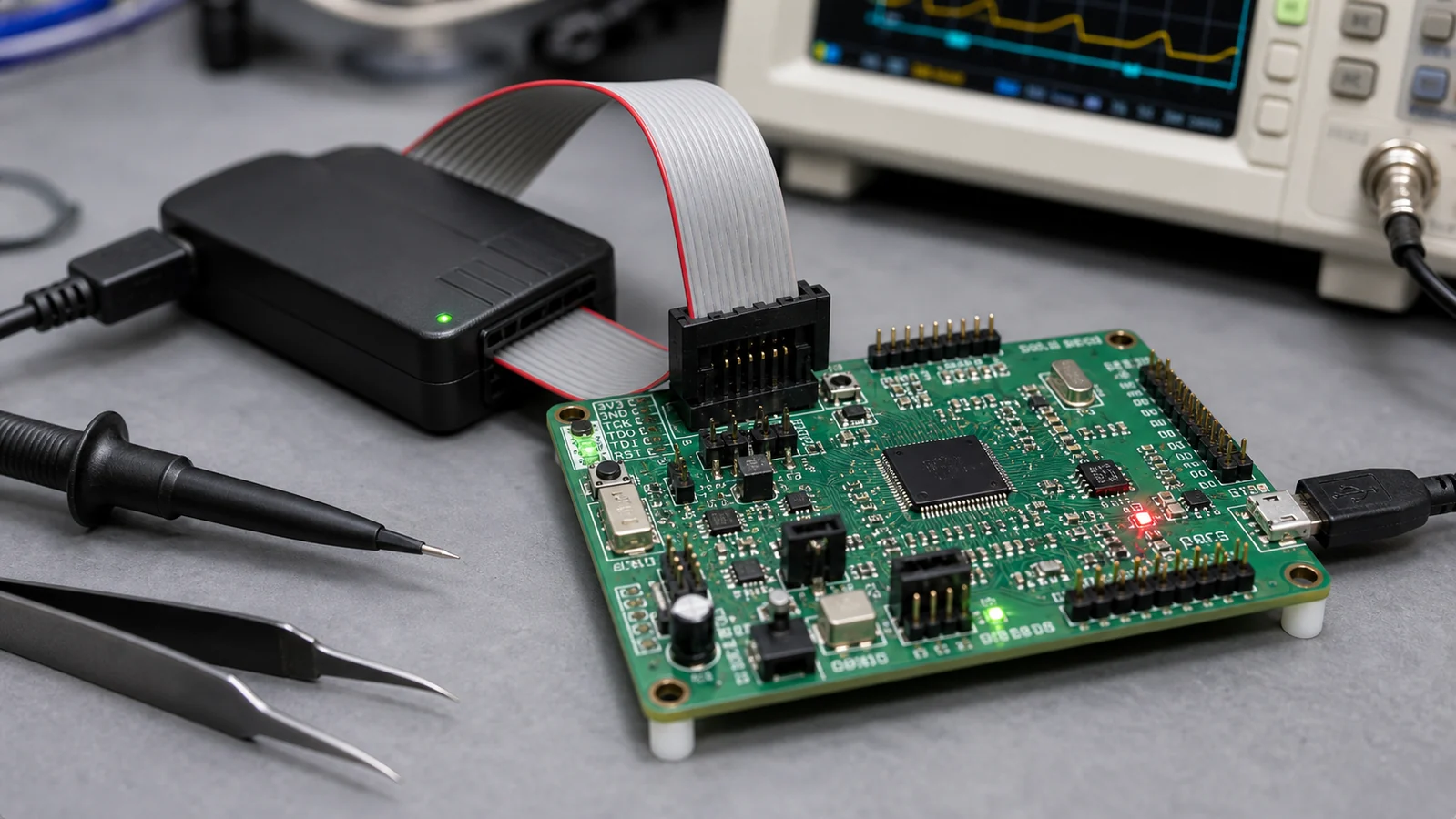
How a PIC Microcontroller Works on a PCB
On a PCB, the microcontroller acts as the control hub. It reads inputs such as switches, sensors, thermistors, encoders, or communication packets. Then it makes decisions based on the firmware and drives outputs such as MOSFETs, displays, relays, buzzers, motors, or status LEDs.
The chip itself is only one part of the design. A usable PIC-based board also needs a clean power rail, reset handling, decoupling capacitors, clocking if the selected part does not use only an internal oscillator, programming access, and enough routing discipline to avoid firmware-debugging problems that are really hardware problems.
For example, a simple thermostat board may use a PIC to read temperature, debounce buttons, and switch a fan relay. A small industrial daughterboard may use a PIC to monitor analog voltages and pass data upstream over UART. In both cases the MCU is central, but the reliability of the board still depends on sound PCB schematic design and layout choices.
Common PIC Microcontroller Applications
PIC microcontrollers are common in products that need predictable control without a large operating system or heavy software stack. Typical examples include appliance controls, small power supplies, sensor modules, handheld test equipment, access control hardware, motor drivers, and automotive subassemblies.
They are also common in repair and reverse-engineering work. A failed board may use a PIC that controls startup timing, safety interlocks, or communication with a host board. If the original board is obsolete, engineers may need to identify the MCU family, trace its support circuits, and decide whether repair, cloning, or functional redesign is the lower-risk path.
PIC parts are not automatically the best choice for every new project. If a product needs high-speed graphics, wireless stacks, or substantial DSP work, another MCU family may be a cleaner fit. But for many control-focused embedded products, a PIC still covers the requirement with less overhead than a larger platform.
Main PIC Families and Selection Differences
The PIC lineup is broad, so the family choice matters more than the brand name alone. Older 8-bit devices are common in simple control boards because they are inexpensive and well understood. Midrange devices add better peripherals and memory depth. Higher-end 16-bit and 32-bit families support more code space, better math performance, and broader interface options.
When comparing parts, check five things first:
1. Available I/O and package size. 2. Required supply voltage and analog performance. 3. Memory size for current firmware and future revisions. 4. Communication interfaces needed by the product. 5. Programming and debugging support during bring-up and service.
It is easy to over-focus on clock speed and miss a more practical issue, such as whether the package pitch is too tight for a low-cost repairable board or whether the selected MCU is locked behind a fragile supply chain. For products that may need long service life, availability can matter more than a small performance gain.
PIC vs Other Microcontrollers
The usual comparison is PIC versus AVR, STM32, MSP430, or an ESP-class device. There is no universal winner because the right answer depends on the job. PIC parts are often favored when a design needs straightforward control logic, mature tooling, and a part family that has been used in similar products for years.
An STM32 may offer more headroom and a richer ecosystem for complex embedded work. An ESP32 may be more attractive if Wi-Fi or Bluetooth is mandatory. AVR parts are still common in Arduino-centric development. But if you are inheriting an older design, reusing a PIC architecture can reduce board changes, firmware rewrite effort, and qualification risk.
That tradeoff is especially important in reverse engineering. A redesign that changes the MCU family may look elegant on paper, but it can also shift pin mapping, interrupt timing, ADC behavior, programming flow, and test coverage. For a service-driven project, stability often beats novelty.
PCB Design Tips for PIC-Based Boards
Start with power integrity. Put decoupling capacitors close to each MCU supply pin, keep the power return short, and avoid routing noisy switching currents through the same local ground path used by sensitive analog pins. Small PIC boards often fail in subtle ways because the hardware around the MCU was treated as an afterthought.
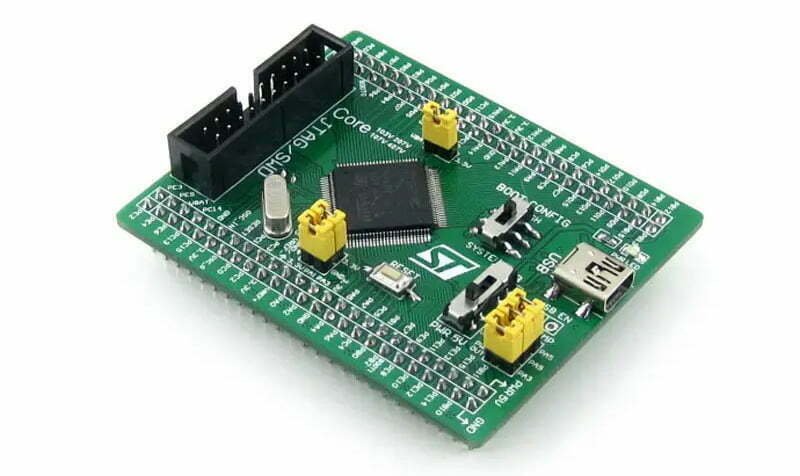
Expose a practical programming header. Whether the team uses ICSP or another supported method, debugging is much easier when the programming pins are accessible and labeled. This is also useful for field service and small-batch rework.
Keep reset and clock circuits conservative. A board that occasionally fails to boot can waste days of firmware investigation. If the design uses an external oscillator, follow the datasheet guidance closely and keep the network physically tight.
Use disciplined placement and routing. General PCB layout guidelines still apply, but PIC boards often benefit from extra attention around analog reference paths, programmer access, and isolation between low-level sensor traces and switching outputs.
If the board is part of a repair or clone effort, document what is known and what is inferred. That includes pin functions, boot behavior, test points, and whether the original device appears protected against code readout. Those details affect whether the project is a repair, a compatible redesign, or a full PCB reverse engineering effort.
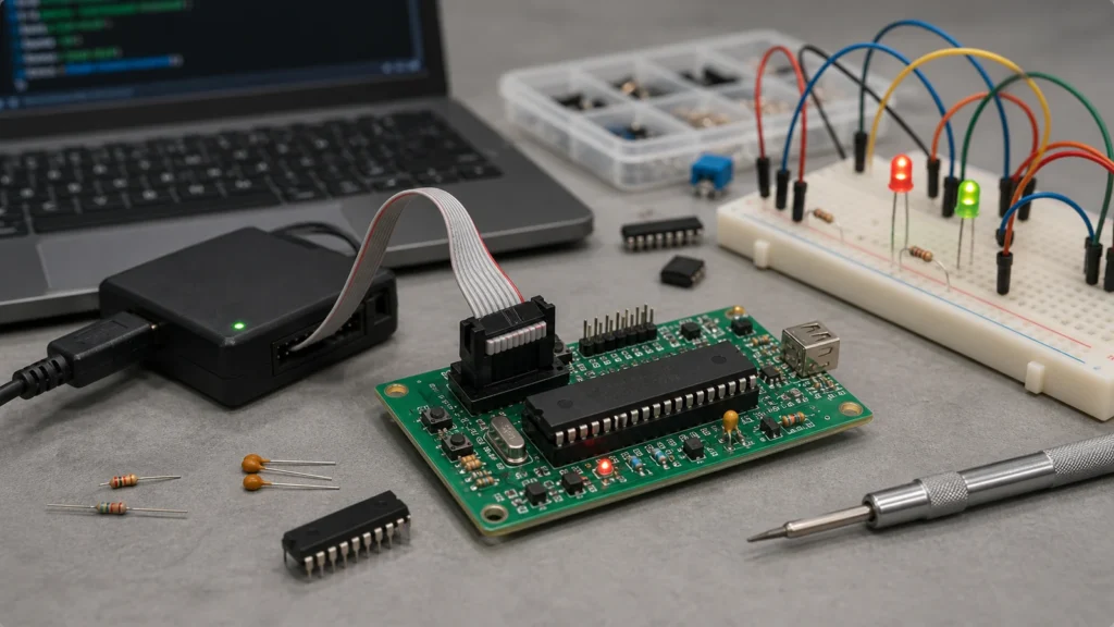
Firmware and Manufacturing Considerations
A microcontroller choice is never only a firmware decision. It affects assembly test, field update procedures, and what the repair team can realistically support later. If the MCU will be programmed in production, define whether that happens before assembly, after assembly, or through a fixture at final test.
It is also worth deciding early how tolerant the design should be to part substitutions. A pin-compatible replacement is helpful only if the firmware image, fuse settings, oscillator assumptions, and peripheral mapping remain valid. Otherwise, a "drop-in" substitute can become a hidden production issue.
For service-heavy products, leave room for diagnosis. A few labeled test pads, a sensible programming connector, and a documented boot path can make a repaired board much easier to verify. Teams offering microcontroller development or board redesign usually spend significant time on those practical details, not just on the code itself.
Common Mistakes When Using a PIC Microcontroller
One common mistake is choosing a part with just enough memory for the first firmware build. That leaves no margin for bug fixes, protocol changes, or future features.
Another is underestimating programming and debug access. Boards sometimes reach prototype stage with no easy way to connect a programmer once the enclosure is assembled. That is preventable.
Designers also get caught by mixed-signal issues. A PIC that reads analog sensors and also switches relays or PWM loads can behave poorly if the ground strategy is sloppy. The symptom may look like random firmware instability when it is really noise coupling into the measurement path.
Finally, some teams pick a PIC because an old design used one, without rechecking present-day availability, toolchain support, and total redesign cost. Reuse is useful, but only when it is still technically and commercially justified.
When a PIC Microcontroller Is the Right Fit
A PIC microcontroller is often the right fit when the product needs dependable embedded control, modest resource requirements, long service life, and a hardware platform that can be supported by a practical engineering workflow. It is also a sensible choice when you are maintaining or recreating an existing board that already depends on a PIC architecture.
If the project needs a clean board spin, firmware support, or reconstruction of an obsolete control board, the better question is not whether PIC is old or new. The better question is whether it solves the real control problem with acceptable risk, cost, and supportability.
For many repair, cloning, and control applications, the answer is still yes.
What should be checked before choosing a PIC microcontroller?
Check I/O count, package, supply voltage, oscillator needs, peripherals, memory, programming method, availability, and long-term lifecycle fit.
Why are decoupling capacitors important for a PIC MCU?
Decoupling capacitors provide local current during switching and help keep the supply stable. Place them close to the MCU power pins with a short return path.
What can stop a PIC board from programming?
Common causes include wrong MCLR wiring, missing reference voltage, overloaded PGC/PGD pins, oscillator problems, bad ground reference, or a programming connector wired in the wrong orientation.