Furnace PCB Board: What It Does and How Failures Are Diagnosed
A furnace PCB board is the control center inside many modern gas, oil, and electric furnaces. It reads safety switches and sensors, starts the ignition sequence, drives relays, controls the blower motor, and shuts the system down if something looks unsafe. When a furnace stops working, the board is often blamed first, but a careful diagnosis usually starts with the entire control circuit.

Replacing the board without testing inputs and loads can waste money. A weak pressure switch, dirty flame sensor, damaged wiring harness, failing transformer, or shorted inducer motor can make a good board look bad. The right approach is to understand what the board does, verify power and signals, and then decide whether the PCB is actually failed.
What a Furnace PCB Board Controls
The furnace board coordinates the heating sequence. A thermostat calls for heat, the board checks safety inputs, starts the inducer, verifies pressure, enables ignition, opens the gas valve, proves flame, and then starts the blower. If one step fails, the board may lock out the system and flash an error code.
On the board itself, you may find relays, connectors, a microcontroller, rectifier diodes, resistors, capacitors, optocouplers, and sometimes triacs or driver ICs. These parts sit on a printed circuit board designed for both low-voltage control and higher-current switching.
Common Failure Symptoms
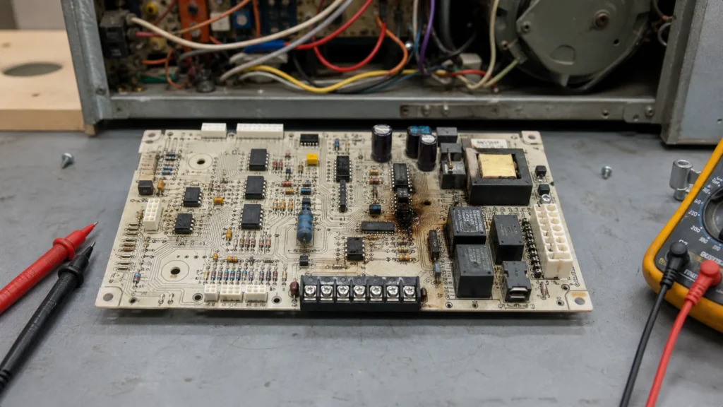
A furnace PCB board may be suspected when the furnace is dead, the blower will not start, the inducer runs continuously, the igniter never energizes, the gas valve does not open, or the board shows no status LED. Burn marks, cracked solder joints, swollen capacitors, and damaged relay contacts are also warning signs.
But symptoms can mislead. If a safety switch is open, the board may be doing exactly what it should. If the transformer output is low, the board may reset repeatedly. If a motor winding is shorted, a replacement board can fail again as soon as it is installed.
Diagnosis Before Replacement
Start with the basics: incoming line voltage, transformer secondary voltage, fuse continuity, thermostat call, connector seating, and visible board damage. Then check the furnace fault code chart. Many boards flash a sequence that points to pressure switch, limit switch, ignition, flame sense, or rollout problems.
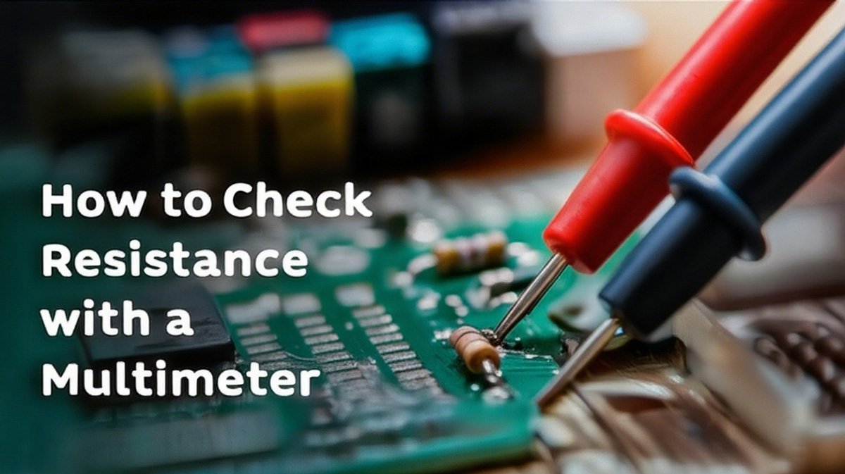
When measuring signals, use the furnace wiring diagram and work carefully around mains voltage. A technician may check whether the board receives the correct input and whether it sends the expected output at the right step. If the input is missing, the problem is outside the board. If the input is present but the output never appears, the board becomes a stronger suspect.
PCB-Level Issues
At PCB level, furnace control boards often fail from heat, vibration, moisture, dust, voltage spikes, or overloaded relay contacts. Cracked solder joints around relays and connector pins are common because those parts see mechanical and thermal stress. Electrolytic capacitors can dry out. Surge events can damage power supply components or microcontroller inputs.
Some failures are repairable by a qualified electronics technician, especially cracked solder joints or discrete component damage. Other failures are not practical to repair because firmware, safety certification, or unavailable custom ICs make board-level repair risky. A professional PCB repair decision should include both electrical function and safety context.
Why Safety Matters
A furnace board is not just a convenience controller. It is part of a safety chain involving flame proving, limit switches, rollout switches, pressure switches, and gas valve control. Bypassing a safety input to "test" the furnace can create a fire, carbon monoxide, or gas hazard.
For this reason, PCB-level repair and HVAC troubleshooting should stay within safe boundaries. It is reasonable to inspect a board, test low-voltage continuity, and identify damaged components. It is not reasonable to defeat safety circuits or install an unknown repaired board without proper functional testing.
Replacement Considerations
If replacement is needed, match the exact board number, furnace model, voltage, blower type, and revision. Some boards require jumper settings or DIP switch configuration. A board that fits physically may still run the wrong blower timing or ignition sequence.
Before installing a new board, check the loads connected to it. A shorted gas valve coil, failing inducer, or damaged wiring can destroy the replacement. Inspect connectors for heat damage and confirm the fuse rating. After installation, run a full heat cycle and verify that the fault code history does not immediately return.
Design Lessons for Control Boards
For product engineers, furnace PCB boards are a reminder that real-world control boards need more than a schematic that works on a bench. They need surge protection, relay derating, isolation spacing, thermal planning, connector retention, and clear diagnostic outputs. Good PCB design service work considers how the board will age in a hot, dusty, vibrating cabinet.
Bottom Line
A furnace PCB board can be the failed part, but it should not be the first and only assumption. Diagnose power, inputs, loads, safety switches, and visible board condition before replacing it. When the board is truly damaged, treat it as both an electronic assembly and a safety-related control component.
What does a furnace PCB board control?
A furnace PCB usually coordinates low-voltage inputs, safety switches, ignition or heating calls, blower timing, relays, and fault monitoring. The exact functions depend on the furnace design, so diagnosis should start with the schematic and measured voltages.
Can a burned relay mean the PCB is the root cause?
Not always. A relay or connector may burn because of a downstream load, loose terminal, motor fault, or repeated overheating. Check the connected circuit before replacing only the board.
What should be checked before replacing a furnace control board?
Verify supply voltage, transformer output, thermostat input, sensor wiring, relay outputs, connector condition, and any visible heat damage. Replacing the board without these checks can leave the original fault in place.