BootLoader is a common word for many people , and it is even used frequently. For example, we need it when upgrading the system online, running the program in the external memory. In this post, we will introduce how to design a BootLoader program for STM32 series MCU.
Basic Principle of BootLoader
Since we want to implement a BootLOader program for STM32, first we must understand the basic principles of the BootLOader program.
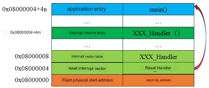
As we know, the BootLOader program must be to achieve system guidance, which is the basic function of the BootLOader program. For the STM32 series MCU, the program will be executed from the start address of the internal Flash memory after the system starts. Then enter the application program and execute it according to the established order. At this time, the BootLoader and the application program are integrated, as shown in the figure:
But sometimes, we don’t want the application to run directly, such as when we want to implement IAP for the system; or we don’t want the application to run in our internal Flash; or the application runs in the internal Flash, but we want The application runs from the internal Flash address we specify and so on. At these times we need a separate BootLoader program. The system first starts the BootLoader program, and enters the application program execution after the system is ready, as shown in the figure:
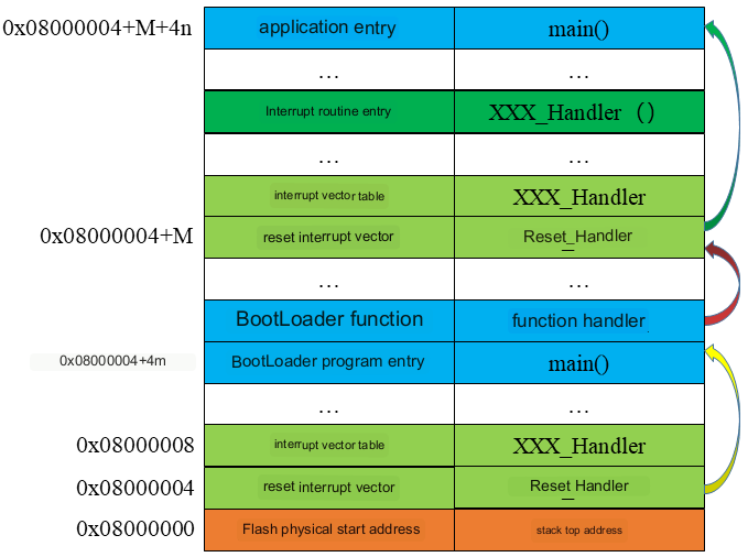
In the picture above, we actually store the application in the specified location of the internal Flash, which is of course to achieve some of our needs, such as system IAP. Of course, we can also store the application program in the external Flash, and then the BootLoader program jumps to the external Flash to execute the application program, but the premise is that the external Flash purchases the execution program. The specific process is as follows:
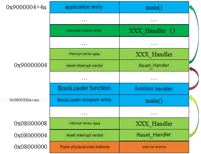
Of course, this is just an example, and we only need to modify the address for different memories. As for the functions to be implemented in the BootLoader program, it depends on the usage. In principle, we can add any function we want, such as hardware detection, system upgrade and so on.
BootLoader Design for STM32
Flash Planning
We use STM32F407IGT6 as the target MCU, which has 1M Flash and 192K SRAM. We divide the Flash into two parts, one is the boot program area (0x0800 0000 – 0x0800 3FFF ) with a size of 16K Bytes, and the rest is the application program area (0x0800 4000 – 0x080F FFFF). The specific distribution is as follows:
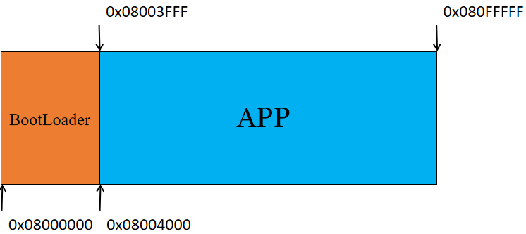
We let the BootLoader program occupy 16K of storage space. But it can operate the entire Flash storage space.
BootLoader Structure
Let’s consider the structure of the BootLoader program. The main purpose of our design of the BootLoader program is to upgrade the application program. So what are the main functions that need to be implemented in the BootLoader program? There are several aspects that must be included. One is the basic configuration, such as the clock, etc., which we implement in the main program; the other is the operation of the Flash, and we will definitely check and write the Flash when we upgrade the application program; It is the jump control program, we need to execute the application program in the end, and the jump function is essential. Of course, there may be other needs according to different needs. Specifically as shown in the figure below:
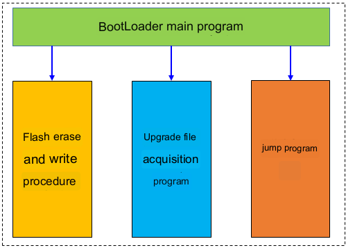
In the figure above, in addition to the three basic implementations of signing, we also added the function of obtaining IAP files. This part of the function is also needed, but there may be a big difference in different modes. Because the way to obtain files can be various types of communication such as Ethernet port, serial port, etc. It can also be various types of memory, such as SD card, U disk and so on. Therefore, although this function is essential, the implementation method is very flexible. In the subsequent implementation, we will analyze specific issues in detail.
BootLoader Implementation
Now, we have determined the division of Flash, and understand the basic workflow of BootLoader. Next, I will discuss how to implement a BootLoader program.
BootLoader Encoding
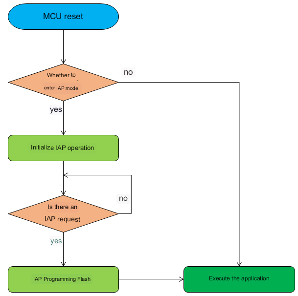
We know that when the chip is powered on, it runs the BootLoader program first, and then jumps to the application program area to execute the application program. Therefore, when we write the BootLoader program, we first judge whether the system has IAP requirements. If there is an IAP request, it will enter the IAP mode. After completion, it will jump to the application program for execution. If there is no IAP request, it will directly jump to the application program for execution. The specific process is as follows:
Regarding the processing of IAP, there will be different processing methods in different situations. Here we mainly take a look at the jump control program. First define the first address of the application and declare a function pointer type. details as follows:
					#define ApplicationAddress 0x08004000 //Application first address definition

typedef void (*pFunction)(void); //Define the jump function pointer type
Some people may ask what defines such a function pointer type, because we finally jump to the Reset_Handler function, so we must have a function pointer that can point to this function. Next we can implement the jump program.
					/*jump to application processing function*/
static void JumpToApplication(void)
{
   uint32_tStackAddr; //Application stack address
   uint32_tResetVector; //The address of the application interrupt vector table

   pFunctionJumpToApp; //Define the jump function pointer

  __set_PRIMASK(1); //Turn off global interrupt

   StackAddr= *(__IO uint32_t*)ApplicationAddress; //0x08004000;
  ResetVector = *(__IO uint32_t*)(ApplicationAddress + 4); //0x08004004;

  if((StackAddr&0x2FFC0000)==0x20000000) //Check whether the stack top address is legal.
   {
    __set_MSP(StackAddr); //Initialize the application stack pointer

    JumpToApp = (pFunction)ResetVector;
    JumpToApp();
   }
}
App Processing
After realizing the coding of BootLoader, if we want to jump to the App to run correctly, we need to modify the App accordingly. There are 2 important changes. If the application is a bare-metal program, we need to enable the global midrange before configuring the clock.
					/*Enable global interrupt, closed in BootLoader*/
 __set_PRIMASK(0);
At the same time, the offset address of the mid-end vector table also needs to be modified. For the STM32F07 we use, it can be modified directly in the system_stm32f4xx.c file.
#define VECT_TAB_OFFSET 0x4000 /*!< Vector Table base offsetfield.
Then, we also need to make necessary modifications in the development environment, taking the IAR EWARM V8.4 we use as an example. Modify the settings of the interrupt vector table and Flash storage area in the icf file. The details are as follows:
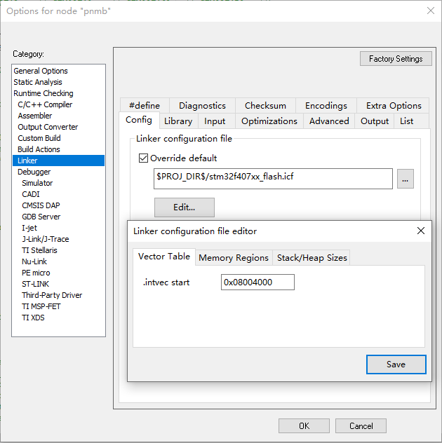
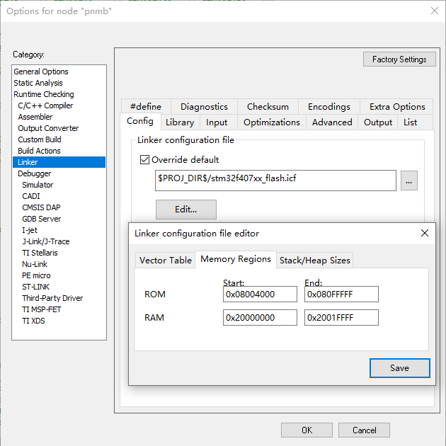
After completing the above configuration, we can download the application program and the BootLoader program to realize the correct jump.
Summary
In this article, we just implemented a simple BootLoader program. After downloading to the target MCU, the jump is realized, and the application program is also running normally, which shows that our design is correct, and various functions can be added on this basis to realize the corresponding IAP application.
It should be noted that we have disabled the global interrupt in the BootLoader program, and remember to enable the global interrupt before the application initializes the system clock, otherwise SystemTick cannot work and a hardware fault (hardfault) will occur. However, if the App is running on the RTOS, it may be wrong to turn on the interrupt, which needs attention.

