Introduction to the 7408 Integrated Circuit
The 7408 Integrated Circuit (IC) is a great tool for building basic logic gates. It is made up of four two-input AND gates, each with individual output terminals. The 7408 IC can be used to create anything from basic Boolean functions to complex logic operations. This versatile chip makes it possible to quickly construct digital systems that are reliable and easy to use. With this IC, the possibilities are virtually limitless. By utilizing the 7408 Integrated Circuit, engineers and hobbyists alike can quickly and easily implement their ideas into reality. By combining this powerful IC with other components, the results can be astounding and offer an unparalleled level of convenience and performance.
Features of 7408 IC
- TTL compatible
- Low power consumption
- High noise immunity
- High-speed switching
- Overloaded protection
- Low noise levels
- Contains 8 input lines and 4 output lines
- Quad 2-input AND gates
- Operating Voltage of 5V
- Output Current of 0.4mA
- Input current of 40uA
- Output Voltage of 0.8V to 4.2V
- Operating temperature of -55°C to 125°C
- Maximum Propagation Delay Time of 8.7ns
IC 7408 pin diagram

The 7408 IC has 14 pins that provide a range of functions, such as enabling logic gates, outputs, and inputs. It is essential to understand the 7408 Pinout before attempting to use the device in any application. Having a good understanding of the pinout can help ensure the device is used correctly and safely.
Pin Descriptions of the 7408 IC

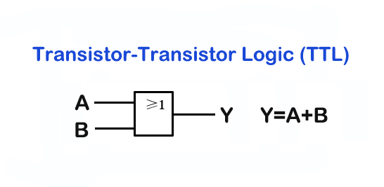
In the logic diagram of 7408, the “A” and “B” is input gate, “Y” is output gate, “GND” is ground, “VCC” is power supply.
7408 IC Electronic Specifications
Configuration:
| Package: | SOIC or PDIP |
| logic family: | TTL |
| Dual-In-Line (DIL): | 14 pin |
| Independent 2−Input AND gates: | 4 |
Absolute Maximum Ratings:
| Maximum Propagation Delay: | 10 ns |
| Operating Temperature: | -55°C to 125°C |
| Storage Temperature Range: | -65°C to +150°C |
| High speed operation: | up to 10 MHz |
Operating Conditions:
| Parameter | Symbol | Min | Typ | Max | Unit |
|---|---|---|---|---|---|
| Supply Voltage | VCC | 4.75 | 5 | 5.25 | V |
| High−Level Input Voltage | VIH | − | − | 2 | V |
| Low−Level Input Voltage | VIL | − | − | 0.8 | V |
| High−Level Output Current | IOH | − | − | −0.8 | mA |
| Low−Level Output Current | IOL | − | − | 16 | mA |
| Operating Temperature Range | TA | -55 | − | 125 | ℃ |
Electrical Characteristics:
| Parameter | Symbol | Test Conditions | Min | Typ | Max | Unit |
|---|---|---|---|---|---|---|
| Input Clamp Voltage | VIK | VCC = MIN, II = −12mA | − | − | −1.5 | V |
| High Level Output Voltage | VOH | VCC = MIN, VIH = 2V, IOH = −0.8mA | 2.4 | 3.4 | − | V |
| Low Level Output Voltage | VOL | VCC = MIN, VIL = 0.8V, IOL = 16mA | − | 0.2 | 0.4 | V |
| Input Current | Ii | VCC = MAX, VI = 5.5V | − | − | 1 | mA |
| High Level Input Current | IIH | VCC = MAX, VI = 2.4V | − | − | 40 | µA |
| Low Level Input Current | IIL | VCC = MAX, VI = 0.4V | − | − | −1.6 | mA |
| Short−Circuit Output Current | IOS | VCC = MAX, Note 4 | −18 | − | −55 | mA |
| High Level Supply Current | ICCH | VCC = MAX, VI = 4.5V | − | 11 | 21 | mA |
| Low Level Supply Current | ICCL | VCC = MAX, VI = 0V | − | 20 | 33 | mA |
Switching Characteristics:
| Parameter | Symbol | Test Conditions | Min | Typ | Max | Unit |
|---|---|---|---|---|---|---|
| Propagation Delay Time LOW-to-HIGH Level Output | tplh | Cl=15pF Rl=400R | − | − | 22 | nS |
| Propagation Delay Time HIGH-to-LOW Level Output | tphl | Cl=15pF Rl=400R | − | − | 15 | nS |
Applications of the 7408 IC
– Digital Logic Gates
– Binary Counters
– Multiplexers
– Flip-flops
– Bus Driver/Receiver
– Address Decoders
– Data Latches
– Logic gate circuits
– Decoders
– Shift registers
– Counters
– Arithmetic circuits
Engineering checks for 7408 IC datasheet and AND gate pinout
Before using 7408 IC datasheet and AND gate pinout in a PCB, firmware, repair, or validation workflow, confirm the details that usually decide whether the design works reliably instead of only reading the headline specification.
Design and troubleshooting checklist
| Area | What to check | Why it matters |
|---|---|---|
| Logic family | Check whether the part is 7408, 74LS08, 74HC08, or 74HCT08 before mixing voltage levels | Input thresholds, output drive, and propagation delay depend on the logic family |
| Pin verification | Confirm VCC on pin 14, GND on pin 7, and the four A/B/Y gate groups before routing | A mirrored DIP or SOIC footprint can damage the IC and connected logic |
| Signal integrity | Add local decoupling, avoid floating inputs, and verify fan-out for downstream loads | TTL and CMOS gates can oscillate or draw excess current when inputs are left undefined |
These checks help connect the search intent around 7408 IC pinout with practical board-level decisions, component selection, and failure analysis.