The TLIMX6U-EVM by Tronlong® Technology is an evaluation board designed around the NXP i.MX 6ULL, featuring an ARM Cortex-A7 high-performance, low-power processor. Consisting of a core board and an evaluation baseboard, the TLIMX6U-EVM has undergone professional PCB layout and rigorous temperature testing, ensuring stability and reliability for various industrial applications.
This article primarily introduces an IoT module development case based on the Tronlong® Technology TLIMX6U-EVM evaluation board. The applicable development environments are as follows:
- Windows Development Environment: Windows 7 64-bit, Windows 10 64-bit
- Virtual Machine: VMware 15.1.0
- Linux Development Environment: Ubuntu 18.04.4 64-bit
- U-Boot: U-Boot-2020.04
- Kernel: Linux-5.4.70
- Linux SDK: 5.4.70_2.3.0
Unless otherwise specified, the default configuration uses USB TO UART1 as the debugging serial port, Linux SD boot mode to start the system, and network connectivity through a router to a PC.
SDIO WIFI Module Testing
This case uses the RTL8189 SDIO WIFI module model. Insert the SDIO WIFI module into the evaluation board’s SDIO interface as shown in the diagram below.
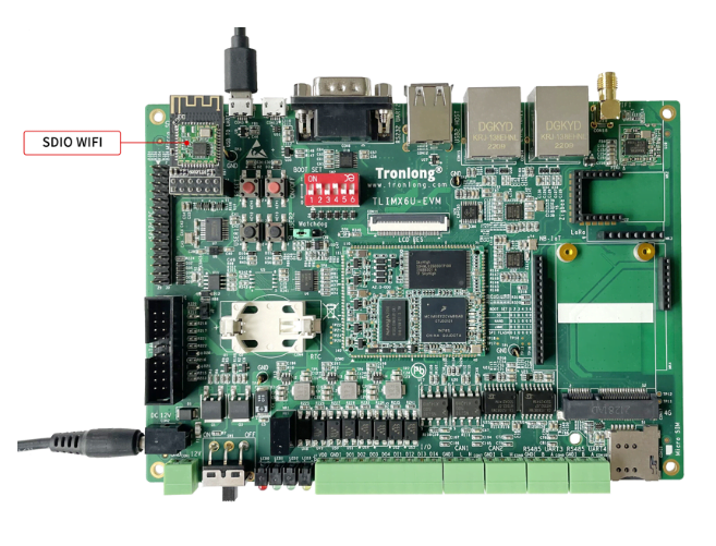
The SDIO WIFI module supports both STA and AP modes:
- STA Mode: In STA mode, the WIFI module can receive signals from wireless routers, enabling internet connectivity through the router.
- AP Mode: In AP mode, the WIFI module creates a wireless LAN hotspot, allowing devices like phones and computers to form a local network.
The test program for this case is located in the product documentation at “4-Software Information\Demo\module-demos\sdio_wifi_test”. The specific details are as follows:
| Directory | Description |
|---|---|
| bin | Test scripts, program configuration files |
| driver | SDIO WIFI module driver |
| src | SDIO WIFI module driver source code |
Copy all files from the “bin” directory and the “driver” directory’s “8189fs.ko” driver file to the same paths in the evaluation board’s file system. Make sure to correctly connect the SDIO WIFI module to the evaluation board’s SDIO interface. Due to pin-sharing between the SDIO interface and the Micro SD interface, remove the Linux SD boot card from the evaluation board’s Micro SD card slot. Set the evaluation board’s boot mode to NAND FLASH boot mode by changing the DIP switch to “011000” (positions 1 to 6).
STA Mode Testing
Access the evaluation board’s file system, navigate to the path where the SDIO WIFI module driver “8189fs.ko” is located, and execute the following command to load the driver:
Target# insmod 8189fs.ko
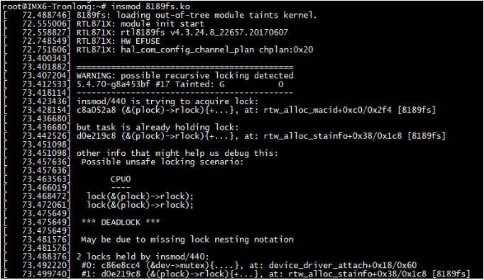
Execute the following commands to disable other networks and the “wpa_supplicant” process, leaving only the WIFI network:
					Target# ifconfig eth0 down
Target# ifconfig eth1 down
Target# killall -9 wpa_supplicant
Target# ifconfig wlan0 up
Target# ifconfig
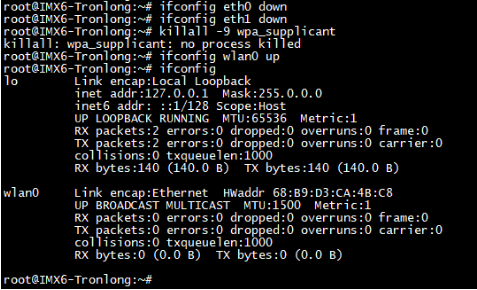
In the directory of the “wifi_setup.sh” file, execute the following command to connect the evaluation board to the router using the WIFI module. Use the “-i” flag to specify the WIFI name and the “-p” flag to specify the WIFI password, modifying them as needed:
Target# ./wifi_setup.sh -i Tronlong-test -p omapl138
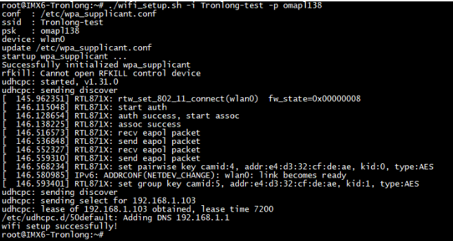
Execute the following command to view the obtained IP address and test communication between the evaluation board and the PC using the “ping” command. Ensure that the evaluation board and PC are on the same local network. Here, 192.168.1.100 represents the actual IP address of the PC.
					Target# ifconfig
Target# ping 192.168.1.100
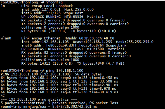
In the evaluation board’s file system, execute the following commands to view the board’s IP address and test network communication bandwidth with the PC using the Iperf3 tool:
					Target# ifconfig
Target# iperf3 -s
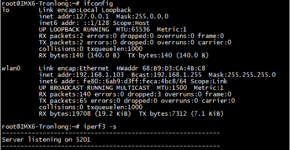
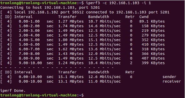
In the Ubuntu system, use the following command to test network communication bandwidth. Replace “192.168.1.103” with the actual IP address of the evaluation board. The test results, which are affected by the network environment, are for reference only.
Host# iperf3 -c 192.168.1.103 -i 1
AP Mode Testing
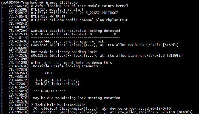
Reboot the evaluation board’s system and execute the following command to load the SDIO WIFI module driver “8189fs.ko”:
Target# insmod 8189fs.ko
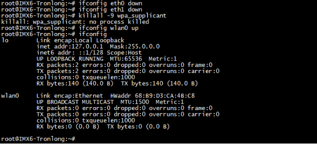
Disable other networks and the “wpa_supplicant” process, leaving only the WIFI network, using similar commands as in the STA mode testing.
					Target#ifconfig eth0 down
Target#ifconfig eth1 down
Target#killall -9 wpa_supplicant
Target#ifconfig wlan0 up
Target#ifconfig
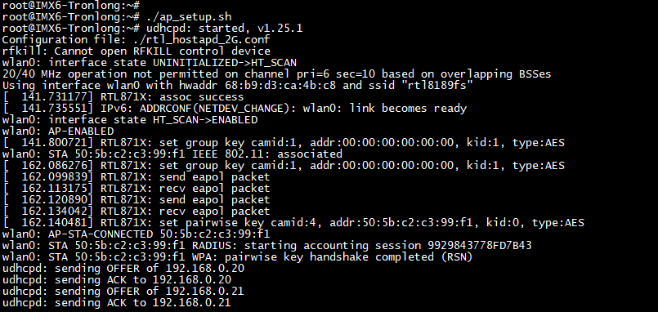
In the directory of the “ap_setup.sh” file, execute the following command to set the SDIO WIFI module to AP mode:
Target# ./ap_setup.sh

If you encounter issues during the AP mode startup due to insufficient random entropy, you need to restart the evaluation board. Execute the following commands to change the entropy pool, and then retry the test:
					Target# mv /dev/random /dev/random_ori
Target# ln -s /dev/urandom /dev/random

The default WIFI name set in the program is “rtl8188fs”, and the password is “88888888”. Modify these settings in the “rtl_hostapd_2G.conf” configuration file. Connect a PC with WIFI capability (such as a laptop or a desktop PC with a USB WIFI adapter) to this wireless LAN hotspot and disconnect any wired network connections. Once connected, the serial debugging terminal will print information about the IP address assigned by Ubuntu. If using a virtual machine with Ubuntu, two IP addresses will be assigned – one for Windows and one for Ubuntu.
Execute the following command to test network connection between wireless LAN devices. If you encounter connection timeouts or failures, consider disabling the PC’s firewall and trying to reconnect:
Target# ping 192.168.0.21 // 192.168.0.21 is the Ubuntu-side IP address

In the evaluation board’s file system, execute the following commands to view the board’s IP address and wait for the PC to connect:
					Target# ifconfig
Target# iperf3 -s
In the Ubuntu system, use the following command to test network communication bandwidth. Replace “192.168.0.1” with the actual IP address of the evaluation board. The test results, which are affected by the network environment, are for reference only.
Host# iperf3 -c 192.168.0.1 -i 1
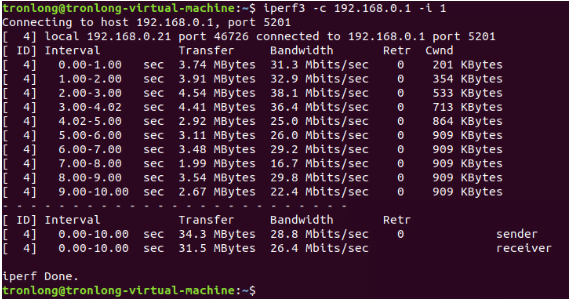
After testing, power off the evaluation board, remove the SDIO WIFI module, and insert the Linux SD boot card into the Micro SD card slot. Set the boot mode DIP switch to “010100” (positions 1 to 6) for SD boot mode.
Compiling the SDIO WIFI Driver
Please copy the driver source code “rtl8189FS.tar.gz” from the “src” directory of the example and place it in your Ubuntu working directory. Then, execute the following commands to extract the source code from the compressed archive:
Host# tar -xf rtl8189FS.tar.gz

Next, navigate to the driver source code directory and modify the top-level “Makefile” using the following commands:
					Host# cd rtl8189FS/
Host# vim Makefile
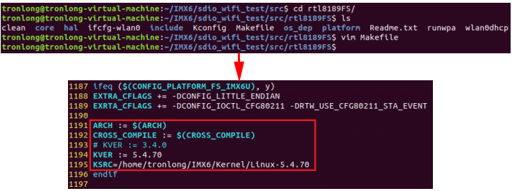
Please modify the contents of the “Makefile” as instructed below:
KSRC = /home/tronlong/IMX6/Kernel/Linux-5.4.70 // Specify the actual path to the kernel source code
In the directory where the driver source code is located, execute the following commands to set up the SDK environment variables and compile the SDIO WIFI driver:
					Host# source /home/tronlong/SDK/environment-setup-cortexa7t2hf-neon-poky-linux-gnueabi
Host# make
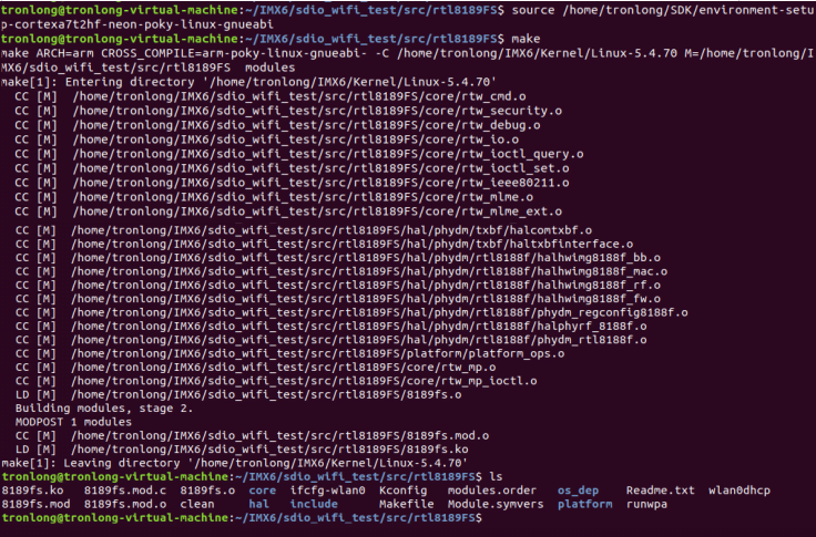
After the compilation is complete, the driver image will be generated in the current directory.


