This article aims to introduce the application of DMA2D mode through the STM32H563 development board. The so-called DMA 2D mode means that the DMA can dynamically adjust the addressing mode and capability of the DMA by setting the intra-block addressing offset and the block addressing offset in advance. In other words, when DMA performs data transmission, the intra-block addressing is no longer always fixed to be stored adjacently, but the address interval for accessing data during two adjacent transmissions can be determined by programming. For repetitive block transfers, it is no longer simply restarting from the same position every time, but the start address of the new transfer can be adjusted according to the offset of the block address.
The principle of DMA 2D transmission
Assume that three transfers are initiated for the same DMA request, corresponding to three DMA transfer blocks.

As shown in the figure above, 5 pieces of data marked in red [that is, the first block] are transmitted for the first time, and data access is performed according to the figure. The second and third times are also similar to the first time, and 5 green data [that is, the second block] and 5 blue data [that is, the third block] are transmitted respectively. Obviously, the data access rules in each transmission block are the same, with two storage spaces separated by two. At the same time, when the second transmission is started after the first transmission is completed, or the third transmission is started after the second transmission is completed, the starting address is set back 14 address spaces from the current position before starting.
How to Use the DMA 2D function?
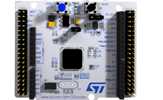
In this example, we uses the STM32H563ZI Nucleo board. And the USART3 of the chip need to be connected with the VCP of the onboard STLINK. Use the serial port debugging assistant on the PC side to distribute three sets of data to the MCU in batches, the contents are 5 characters R, 5 characters G and 5 characters B. Enable the DMA 2D function received by USART3.
By the way, as a reminder, not all channels of the GPDMA of the STM32H5 series support the DMA 2D addressing function. Whether the DMA channel supports 2D function has been clearly written in the CubeMx configuration interface. If you use CubeMx configuration, you can choose the appropriate words. Here I choose DMA CH6 of GPDMA1, which supports DMA 2D function.
The basic configuration for using STM32CubeMX is as follows:

The focus of our configuration is 2D addressing, the details are as follows:
Now it is USART3DMA receiving, obviously the source address is fixed, that is, the USART3 receiving data register, so the offset related to the source address here is 0. The destination address of DMA access is memory, which is variable. Every time one piece of data is stored in the block, it is shifted forward by two positions, corresponding to the Destination Address Offset value below. When the next round of transmission starts after each block transmission is completed, the start address is exactly 14 positions back, corresponding to the following Block Destination Address Offset value, the back is negative, and the forward is positive. Here, a total of 3 block transfers are repeated, corresponding to the Repeat counter value below.

In fact, after 3 rounds of repeated DMA block transmission, the received data looks like the pattern indicated by the arrow in the figure below.

Use STM32CubeMx to complete the configuration, add user code to debug and verify. The user code that needs to be added manually is mainly the following two lines:
					__HAL_LINKDMA(&huart3, hdmarx, handle_GPDMA1_Channel6);

HAL_UART_Receive_DMA(&huart3,(uint8_t *)aRxBuffer, 5); //Receive 5 data per block
The following figure is the result based on debugging. Through three independent DMA receptions, the data is regularly stored in RGB order.