Programming and debugging with simulators can be a great way to get started with the SAMD21 microcontroller. It provides a great platform for those who are new to embedded systems and want to get a better understanding of how they work. By utilizing a variety of simulators, it is possible to develop projects and applications quickly and easily. Through a combination of tutorials, hands-on experience, you can get up to speed on the basics of SAMD21 programming in no time. In this post, you’ll learn types of the SAMD21simulators, debug programs on simulators, SAMD21 code examples and more.
What is SAMD21 Simulator?
The SAMD21 Simulator is a computer program that allows users to simulate the behavior of a SAMD21 microcontroller. This simulator can be used for testing programs for the SAMD21 processor or to develop embedded applications. It provides an environment to debug and test programs on the SAMD21 microcontroller, without the need for physical hardware. It includes a range of peripherals, such as UART, SPI, I2C, timers, and pulse-width modulators. The simulator also includes an IDE with an assembler, compiler, and debugger. For example, if a user is developing a program for a SAMD21-based device, they can use the simulator to test the program and debug it without the need for physical hardware.
Types of Simulators for SAMD21
Simulators are computer programs that simulate the behavior of a physical system. They are often used for embedded systems programming, as they allow for testing code without the need for physical hardware. Simulators for the SAMD21 include Arduino Create, Proteus, and QEMU.
Atmel Studio 7
Atmel Studio 7 is an integrated development platform (IDP) developed by Atmel, a leading microcontroller manufacturer. It is a powerful development environment that allows users to write, compile, debug, and deploy applications for Atmel AVR and ARM microcontrollers. It supports a wide range of development boards and provides graphical user interface (GUI) tools for coding, debugging, and programming. It also has a full suite of tools for software debugging, trace analysis, and simulation. Examples of features include debugging, in-circuit emulator, code editor, device programming, and version control systems.
Proteus
Proteus is a simulator that can be used to simulate a variety of embedded systems, including the SAMD21. It supports a wide range of components, including sensors, actuators, and displays. It also provides debugging tools and allows for code execution on the simulated hardware.
QEMU
QEMU is an open-source simulator that is commonly used for embedded systems programming. It supports a wide range of architectures, including ARM, and can be used to simulate the SAMD21. It provides debugging tools and is often used for testing code without the need for physical hardware.
How to Debug the SAMD21 Program with Simulators?
Debugging is an important part of SAMD21 programming. It allows you to find and fix errors in your code before they cause problems with your project. Using the debugger and the serial monitor can be a great way to troubleshoot code and find errors in your program. It is important to make sure that you have a good understanding of how these tools work before you begin debugging your code. Here we provide an example on the Atmel Studio 7 simulator:
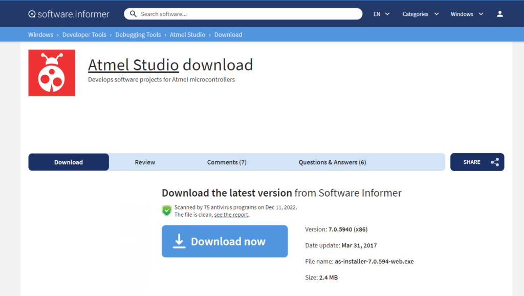
1). Download and install a compatible software package for the SAMD21 microcontroller. Atmel Studio 7 is one example of such software and it can be downloaded from the Atmel website or the following URL.
https://atmel-studio.software.informer.com/download/

2). Create a new project in Atmel Studio 7 by selecting “File” -> “New” -> “Project”. Choose the “GCC C ASF Board Project” option and click “OK”.


3). Choose the board and microcontroller you will be simulating. In this example, we will use the SAMD21 Xplained Pro board and the ATSAMD21J18A microcontroller.

4). In the “ASF Wizard” dialog box, search and select “SERCOM USART” driver. Then click “Apply” to generate the project.


5). Now you can start coding your project. In this example, we will write a simple program that sends and receives data via the USART interface. The program will send the string “Hello World” and then wait for incoming data. The code editor window is typically located in the center of the Atmel Studio user interface. If you don’t see the code editor window, you can open it by double-clicking on the .c file you added to your project in the Solution Explorer pane. Alternatively, you can select the file in the Solution Explorer pane and then click “View” > “Code” from the menu bar to open the code editor window.

					#include <asf.h>

int main (void)
{
  /* Initialize the system */
  system_init();

  /* Initialize the USART interface */
  struct usart_module usart_instance;
  struct usart_config config_usart;
  usart_get_config_defaults(&config_usart);
  config_usart.baudrate    = 9600;
  config_usart.mux_setting = USART_RX_3_TX_2_XCK_3;
  config_usart.pinmux_pad0 = PINMUX_PB08C_SERCOM4_PAD0;
  config_usart.pinmux_pad1 = PINMUX_PB09C_SERCOM4_PAD1;
  config_usart.pinmux_pad2 = PINMUX_UNUSED;
  config_usart.pinmux_pad3 = PINMUX_UNUSED;
  while (usart_init(&usart_instance, SERCOM4, &config_usart) != STATUS_OK);

  /* Send a message */
  char tx_buffer[] = "Hello World!\r\n";
  usart_write_buffer_wait(&usart_instance, (uint8_t *)tx_buffer, sizeof(tx_buffer));

  /* Wait for incoming data */
  while (1) {
    uint8_t rx_byte;
    while (usart_read_wait(&usart_instance, &rx_byte) != STATUS_OK);
    usart_write_wait(&usart_instance, rx_byte);
  }
}
6). Build and run the program in the simulator by selecting “Debug” -> “Start Debugging and Break” from the menu bar. You can then step through the code and watch the values of variables in the “Watch” window.

That’s it! You can now use the SAMD21 simulator to test and debug your microcontroller projects.
Extra SAMD21 Code Examples
In general, samd21 code examples can be found in the Atmel Software Framework and the Atmel mbed Online Compiler. Additionally, whether if they work normally depends on the development board being used. Here are some basic examples:
Blinking LED:
					#include <Arduino.h>

#define LED_PIN 13

void setup() {
  pinMode(LED_PIN, OUTPUT);
}

void loop() {
  digitalWrite(LED_PIN, HIGH);
  delay(1000);
  digitalWrite(LED_PIN, LOW);
  delay(1000);
}
Analog Input Reading:
					#include <Arduino.h>

#define ANALOG_PIN A0

void setup() {
  Serial.begin(9600);
}

void loop() {
  int sensorValue = analogRead(ANALOG_PIN);
  float voltage = sensorValue * (3.3 / 1023.0);
  Serial.print("Sensor Value: ");
  Serial.print(sensorValue);
  Serial.print(", Voltage: ");
  Serial.println(voltage);
  delay(1000);
}
Servo Control:
					#include <Arduino.h>
#include <Servo.h>

#define SERVO_PIN 9

Servo myservo;

void setup() {
  myservo.attach(SERVO_PIN);
}

void loop() {
  myservo.write(0);
  delay(1000);
  myservo.write(90);
  delay(1000);
  myservo.write(180);
  delay(1000);
}
Interrupt Example:
					#include <Arduino.h>

#define INTERRUPT_PIN 2

volatile int counter = 0;

void setup() {
  pinMode(INTERRUPT_PIN, INPUT_PULLUP);
  attachInterrupt(digitalPinToInterrupt(INTERRUPT_PIN), interruptHandler, FALLING);
  Serial.begin(9600);
}

void loop() {
  Serial.println(counter);
  delay(1000);
}

void interruptHandler() {
  counter++;
}
Comparing SAMD21 to STM32
Microcontrollers like the SAMD21 and STM32 are very similar in many ways. Both are 32-bit microcontrollers based on ARM® Cortex™-M0+ cores and have a wide range of peripheral features. However, there are also some key differences between the two. The details are showed as below table:
| Feature | SAMD21 | STM32 |
|---|---|---|
| Processor | ARM Cortex-M0+ | ARM Cortex-M |
| SRAM | 32KB | Up to 128KB |
| Flash Memory | 128KB | Up to 1MB |
| Clock Frequency | 48 MHz | 16-32 MHz (depending on model) |
| GPIO Pins | 33 | Up to 82 |
| Communication protocols | SPI, I2C, UART | CAN, USB, Ethernet, SPI, I2C, UART |
| Power Efficiency | Lower power consumption, sleep mode, and designed to run at lower clock speeds | Consumes slightly more power (2-3mA/MHz) |
| Advanced Features | Fewer | Built-in floating point unit, DDR memory controller, and multiple serial interfaces |
| Price | More cost-effective | More expensive, better suited for more complex applications |