Are you looking for an efficient and high-quality audio amplifier board that can enhance the sound quality of your audio devices? Look no further than the PAM8403 Amplifier Board – a powerful and versatile audio amplifier that’s perfect for DIY audio projects. This compact and easy-to-use board is designed to deliver crisp, clear and high-fidelity audio output, thanks to its advanced pulse code modulation (PCM) technology. Whether you’re building your own portable speaker system, upgrading your car audio system or simply looking to improve the audio quality of your computer, the PAM8403 Amplifier Board is an excellent choice. In this article, we’ll take a closer look at the PAM8403 amplifier board, its features, and how to get the most out of it.
Introduce to PAM8403 IC
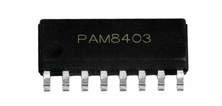
PAM8403 is a commonly used low-voltage stereo digital power amplifier IC. Its operating voltage range is 2.5~5.5V. It can be powered by a single-cell 18650 lithium battery or a 5V mobile phone charger, and its efficiency is not less than 90%. When the power supply voltage is 5V and the speaker is 4Ω, the output power can reach 2x3W. It’s widely used in portable audio devices such as Bluetooth speakers, MP3 players, and headphones.
Features
- High efficiency of up to 90%, reducing power consumption and heat dissipation.
- Dual-channel configuration;
- Excellent distortion performance;
- High signal-to-noise ratio (SNR);
- Excellent power supply rejection ratio (PSRR);
- Built-in over-temperature, overcurrent, and under-voltage protection circuits;
Parameters
- Size: 1.2mm x 1.7mm;
- Power supply: 5V;
- Operates voltage: 2.5V to 5.5V;
- Maximum output power: 3W per channel;
- SNR: 85dB at a 1W output power;
- PSRR: 75dB at 1kHz;
- Drive speakers: low impedance of 4 ohms;
- Total harmonic distortion plus noise (THD+N): less than 0.1%;
Pinout
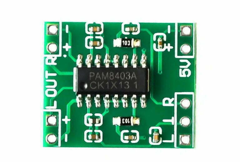
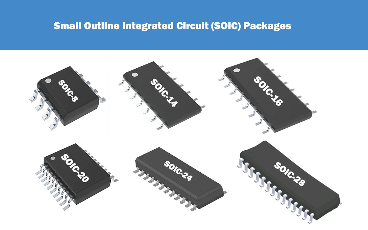
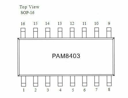
PAM8403 uses SOP-16 package, its 7 pins and 10 pins are left and right channel input terminals, 1 pin and 3 pins are left channel output terminals, 14 pins and 16 pins are right channel output terminals.
Principle of the Amplifier
Digital power amplifier is generally composed of several parts such as pulse generator, PWM circuit, switching amplifier and demodulator. The pulse generator generates a square wave signal with a duty cycle of 50%. The audio signal is input from the Vin terminal, and the pulse width modulation is performed on the square wave signal output by the pulse generator, so that the pulse width is proportional to the amplitude of the input audio signal. width modulated pulse signal. After the signal is amplified by the switching amplifier (the power tube works in the switch state), and then demodulated by the low-pass filter, the speaker can be driven to work. This is the basic working principle of the digital power amplifier.

PAM8403 Amplifier Board
The PAM8403 amplifier board is a small electronic circuit board designed to amplify audio signals. It is commonly used in DIY audio projects, portable speakers, and other audio-related applications.
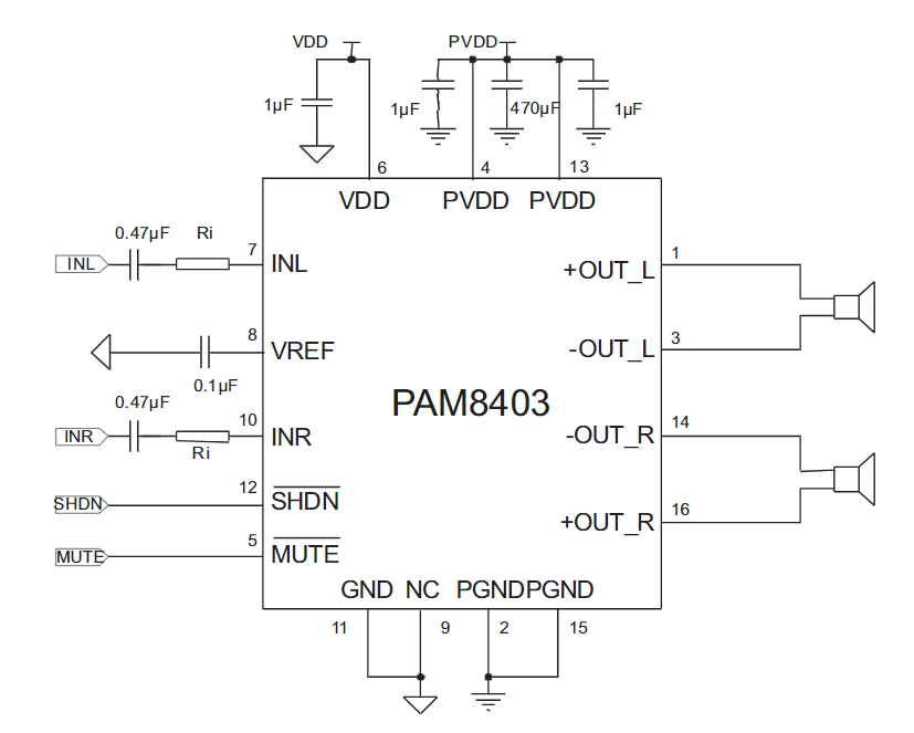
Circuit Diagram
It is capable of delivering up to 3 watts of power per channel and operates on a voltage range of 2.5 to 5.5 volts.
Pin Description
| Pin Number | Pin Name | Description |
|---|---|---|
| 1 | +OUT_L | Left Channel Positive Output |
| 2 | PGND | Power GND |
| 3 | -OUT_L | Left Channel Negative Output |
| 4 | PVDD | Power VDD |
| 5 | MUTE | Mute Control Input (active low) |
| 6 | VDD | Analog VDD |
| 7 | INL | Left Channel Input |
| 8 | VREF | Internal analog reference, connect a bypass capacitor from VREF to GND |
| 9 | NC | No connect |
| 10 | INR | Right Channel Input |
| 11 | GND | Analog GND |
| 12 | SHDN | Shutdown Control Input (active low) |
| 13 | PVDD | Power VDD |
| 14 | -OUT_R | Right Channel Negative Output |
| 15 | PGND | Power GND |
| 16 | +OUT_R | Right Channel Positive Output |
How to Use PAM8403 Amplifier Board?
Below is an easy example of how to use the PAM8403 amplifier board, you should be able to master all these steps.
First of all, let’s learn from a diagram to help you understand how to connect the PAM8403 amplifier board:
					+------------------------+
|                        |
|        Audio Source    |
|        (e.g. phone     |
|         or computer)   |
|           +-----+      |
|           |     |      |
|           |  o--+------+---> IN+
|           |     |      |
|           +-----+      |
|                        |
+------------------------+

     PAM8403 Amplifier Board

+------------------------+
|                        |
|        Speakers or     |
|        Headphones      |
|           +-----+      |
|    OUT+---+     |      |
|           |  o--+------+---> + lead of speaker/headphone
|           |     |      |
|    OUT----+-----+      |
|                        |
|           +-----+      |
|           |     |      |
|           |  o--+------+---> - lead of speaker/headphone
|           |     |      |
|           +-----+      |
|                        |
+------------------------+
Explanation:
The audio source is connected to the IN+ and IN- pins on the PAM8403 board, which is where the input signal is received.
The speakers or headphones are connected to the OUT+ and OUT- pins on the PAM8403 board, which is where the amplified signal is output.
The volume can be adjusted using the volume knob on the board.
Step 1: Gather Materials
First, gather all necessary materials for the project. This includes:
- PAM8403 amplifier board
- Power source (e.g. battery or AC adapter)
- Audio source (e.g. phone or computer)
- Speakers or headphones
- Wires for connecting components
Step 2: Connect Power Source
Connect the power source to the PAM8403 amplifier board. The board can handle a voltage range of 2.5V to 5V, so make sure your power source falls within this range. You can use a battery or AC adapter to power the board.
Step 3: Connect Audio Source
Connect the audio source to the PAM8403 amplifier board. You can use a 3.5mm audio cable to connect your phone or computer to the board. Make sure to connect the audio input to the IN+ and IN- pins on the board.
Step 4: Connect Speakers or Headphones
Connect your speakers or headphones to the PAM8403 amplifier board. You can use wires to connect your speakers to the OUT+ and OUT- pins on the board. Make sure to connect the positive and negative leads to the correct pins.
Step 5: Power On the Board
Power on the board using the power source. The LED indicator on the board should light up, indicating that the board is receiving power.
Step 6: Adjust Volume
Adjust the volume using the volume knob on the board. Start with the volume low and gradually increase it until you reach your desired volume level.
Step 7: Enjoy Your Audio
Once everything is connected and powered on, you should be able to enjoy your audio through your speakers or headphones. If you’re experiencing any issues with the sound, double-check your connections and make sure everything is securely plugged in.
PAM8403 vs PAM8610
PAM8403 and PAM8610 are both popular audio amplifier chips, the table compares their features. The key difference among them is their output power. The PAM8403 can output 3 watts of power, while the PAM8610 is 15 watts. This makes the PAM8610 more suitable for larger speakers and systems that require higher power output.
| Feature | PAM8403 | PAM8610 |
|---|---|---|
| Number of Channels | 2 | 2 |
| Output Power | 3W | 15W |
| Operating Voltage | 2.5V - 5.5V | 6V - 15V |
| Efficiency | ≥90% | ≥90% |
| THD | ≤0.1% | ≤0.1% |
| SNR | ≥90dB | ≥90dB |
| Package Type | SOIC-16 | QFN-32 |
Conclusion
In this post, we make an introduce to PAM8403 amplifier board, including it’s circuit structure, use, application and more. It is easy to use and requires minimal external components, making it an ideal choice for beginners as well as experienced audio enthusiasts.

