What is LM358?
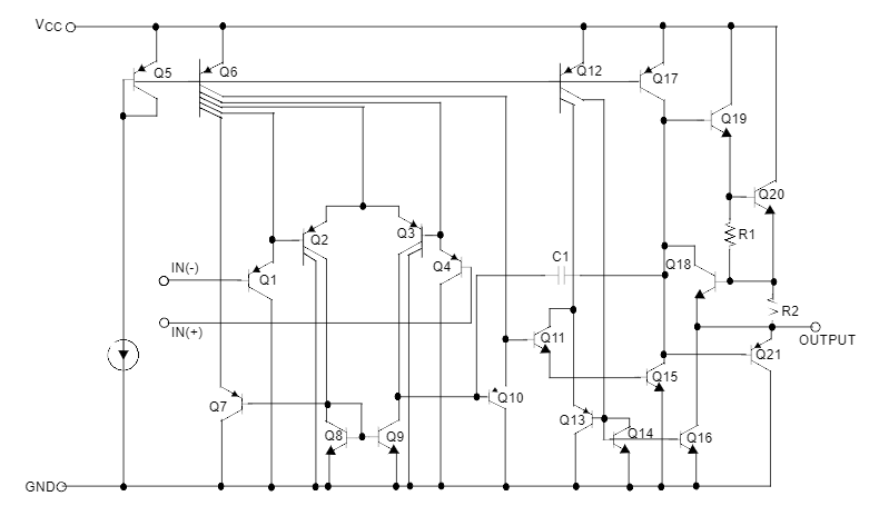
LM358 is a dual operational amplifier that is commonly used in electronic circuits. It is designed to operate from a single power supply over a wide range of voltages. The LM358 is known for its low power consumption, high gain, and wide bandwidth capabilities. It is commonly used in audio amplifiers, signal conditioning circuits, and voltage comparators.
LM358 Pinout
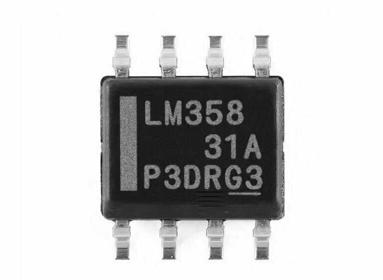
The LM358 has a total of 8 pins, each with a different function, as shown in the following pin diagram and description.

Pin Description
| Pin Number | Pin Name | Description |
|---|---|---|
| 1 and 7 | Output | the outputs of the comparator |
| 2 and 6 | Input(-) | inverting inputs |
| 3 and 5 | Input(+) | in-phase inputs |
| 4 | GND | Ground |
| 8 | VCC | Positive power supply (5-32V) |
LM358 Specification
- Input bias current: 45 nA
- Input detuning current: 50 nA
- Low supply current: – 700 uA
- Single supply voltage: – 3 V to 32 V
- Dual supply voltage: – ±1.5 V to ±16 V
- Input detuning voltage: 2.9 mV
- Input differential voltage: ±32 V
- Input Common Mode Voltage: -0.3 V to 32 V
- Common-mode rejection ratio: 80 d
- Power supply rejection ratio: 100 d
- Operating temperature – 0˚C to 70˚C
- Storage temperature – 65˚C to 150˚C
- Package option: 8-DIP, 8-SOP
How does LM358 Work?
The working principle of the LM358 op-amp is quite simple. The amplifier has two inputs, one is the inverting input (marked as “-” on the IC) and the other is the non-inverting input (marked as “+” on the IC).
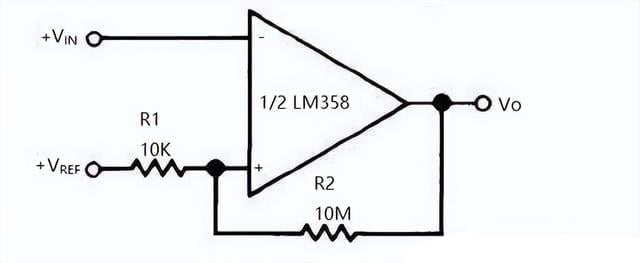
When a voltage is applied to the non-inverting input, it is compared with the voltage applied to the inverting input. Depending on the difference in voltage between the two inputs, the output of the amplifier goes either high or low. If the voltage at the non-inverting input is higher than the voltage at the inverting input, the output of the amplifier goes high. Conversely, if the voltage at the inverting input is higher than the non-inverting input, the output of the amplifier goes low.

The gain of the LM358 op-amp can be adjusted by connecting a feedback resistor between the output and the inverting input. The gain of the amplifier is given by the formula:
Gain = -Rf / Rin
Where Rf is the feedback resistor and Rin is the input resistor.
LM358 Package Size


LM358 Application
- Sensing Amplifier
- DC Gain Module
- Audio amplifier
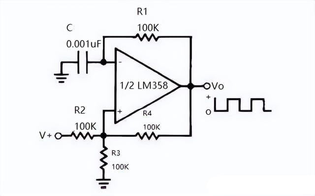
- Active Filters
- Voltage Followers
- Digital Multimeter
- Oscilloscopes
- Comparator
- Loop Transmitter


