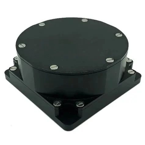
Fiber Optic Gyroscopes (FOG) have become a cornerstone technology in modern navigation and attitude control systems due to their exceptional precision and reliability. These gyroscopes play an essential role in a variety of fields, including aerospace, military, and marine applications, where high accuracy and stability are critical. In this article, we will explore the definition, types, structure, working principle, advantages, and future applications of fiber optic gyroscopes.
What is a Fiber Optic Gyroscope (FOG)?
A Fiber Optic Gyroscope (FOG) is a type of sensor used to measure angular velocity (rotation rate). Unlike traditional mechanical gyroscopes that rely on moving parts, fiber optic gyroscopes are based on optical technology. They utilize the propagation of light through optical fibers to detect rotation. These gyroscopes are known for their high precision, stability, and reliability, making them crucial in applications that require precise orientation and navigation, such as aerospace, marine, and military systems.

Working Principle of FOG
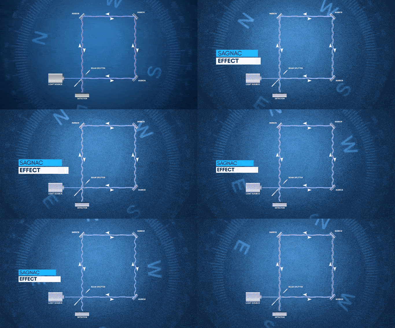
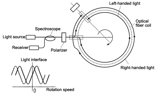
The working principle of the fiber optic gyroscope (FOG) is based on the Sagnac effect, an interference phenomenon caused by rotation. First proposed by French physicist Georges Sagnac in 1913, the Sagnac effect is primarily observed in a device known as a ring interferometer (or Sagnac interferometer). It describes the behavior of light as it propagates along a closed loop. When the system is rotating, two beams of light traveling in opposite directions around the loop will experience different travel times, causing a phase shift between them. This phase shift is directly proportional to the angular velocity of the rotating system.

Sagnac Effect
In a closed-loop optical path, light from a single source is split into two beams, which travel in opposite directions along the loop. When the system rotates, the two beams cover different distances and thus experience different travel times, leading to a phase difference when they meet at the detector. This phase shift is directly related to the angular velocity of the rotation.

Formula Description
The mathematical model of the Sagnac effect can be expressed as follows:
Where:
- ΔϕR is the phase difference between the two light beams.
- A is the area of the optical fiber loop.
- Ω is the angular velocity (the input rotational speed) of the system.
- λ is the wavelength of the laser light.
- c is the speed of light.
Types of Fiber Optic Gyroscopes
Photoelectric Fiber Optic Gyroscopes:
These use optical sensors to measure angular velocity, providing high precision in angle, angular speed, and acceleration measurements.
Electromagnetic Fiber Optic Gyroscopes:
These rely on electromagnetic forces to detect rotational speed and angle, typically used for precision angle and speed measurements.
Laser Fiber Optic Gyroscopes:
These utilize laser light to measure angular velocity, offering high accuracy for dynamic measurements.
Self-oscillating Fiber Optic Gyroscopes:
These use self-oscillating sensors to measure rotational movements.
Capacitive Fiber Optic Gyroscopes:
These measure angular velocity using capacitive sensors to detect minute changes in rotation.
Structure of Fiber Optic Gyroscopes

A typical fiber optic gyroscope consists of three main components:
- Light Source: This is usually a semiconductor laser or an infrared laser that generates the light needed for the system.
- Light Sensor: This includes detectors such as photodiodes or light-sensitive resistors, which detect changes in light intensity due to phase shifts caused by rotation.
- Gyroscope Mechanism: This is the system that controls the rotation of the fiber optic loop, which can be adjusted using motors or actuators.
The fiber optic loop is the core of the gyroscope. When the system is rotated, the light traveling through the loop experiences a phase difference, which is then measured by the light sensor.
Advantages of Fiber Optic Gyroscopes
- High Precision:
Fiber optic gyroscopes provide extremely accurate measurements of rotational speed, far surpassing traditional mechanical gyroscopes in terms of precision.
- No Moving Parts:
Since there are no mechanical components involved, fiber optic gyroscopes avoid issues related to wear and friction, resulting in lower maintenance needs and longer lifespans.
- Strong Anti-Interference Capability:
These gyroscopes can withstand environmental factors such as temperature variations and vibrations, making them ideal for use in harsh conditions.
- Compact and Lightweight:
With advances in fiber optic technology, these gyroscopes are becoming smaller and more portable, making them suitable for integration into compact devices and high-precision instruments.
Applications of Fiber Optic Gyroscopes
- Smart Robotics:
Fiber optic gyroscopes will enable robots to perform more precise movements and quickly gather environmental data, enhancing their ability to complete complex tasks.
- Autonomous Vehicles:
These gyroscopes will play a critical role in autonomous driving systems by providing accurate positioning and path planning, helping reduce the likelihood of accidents.
- Aerospace:
In the aerospace industry, fiber optic gyroscopes will assist in more precise navigation and positioning of spacecraft, ensuring safer and more efficient space missions.


