Energy efficient ethernet sounds like a switch feature until a board team has to explain why one link saves power cleanly and another wakes late, drops packets during bring-up, or refuses to show meaningful current reduction on the bench. IEEE 802.3az is real, but the practical result depends on whether the PHY, magnetics, firmware defaults, and link partner all enter and exit low-power idle in a controlled way.
This guide narrows the topic to what engineers actually need: how Energy Efficient Ethernet changes board-level design reviews, what to probe during validation, and when the feature helps enough to keep versus when it becomes a support burden.
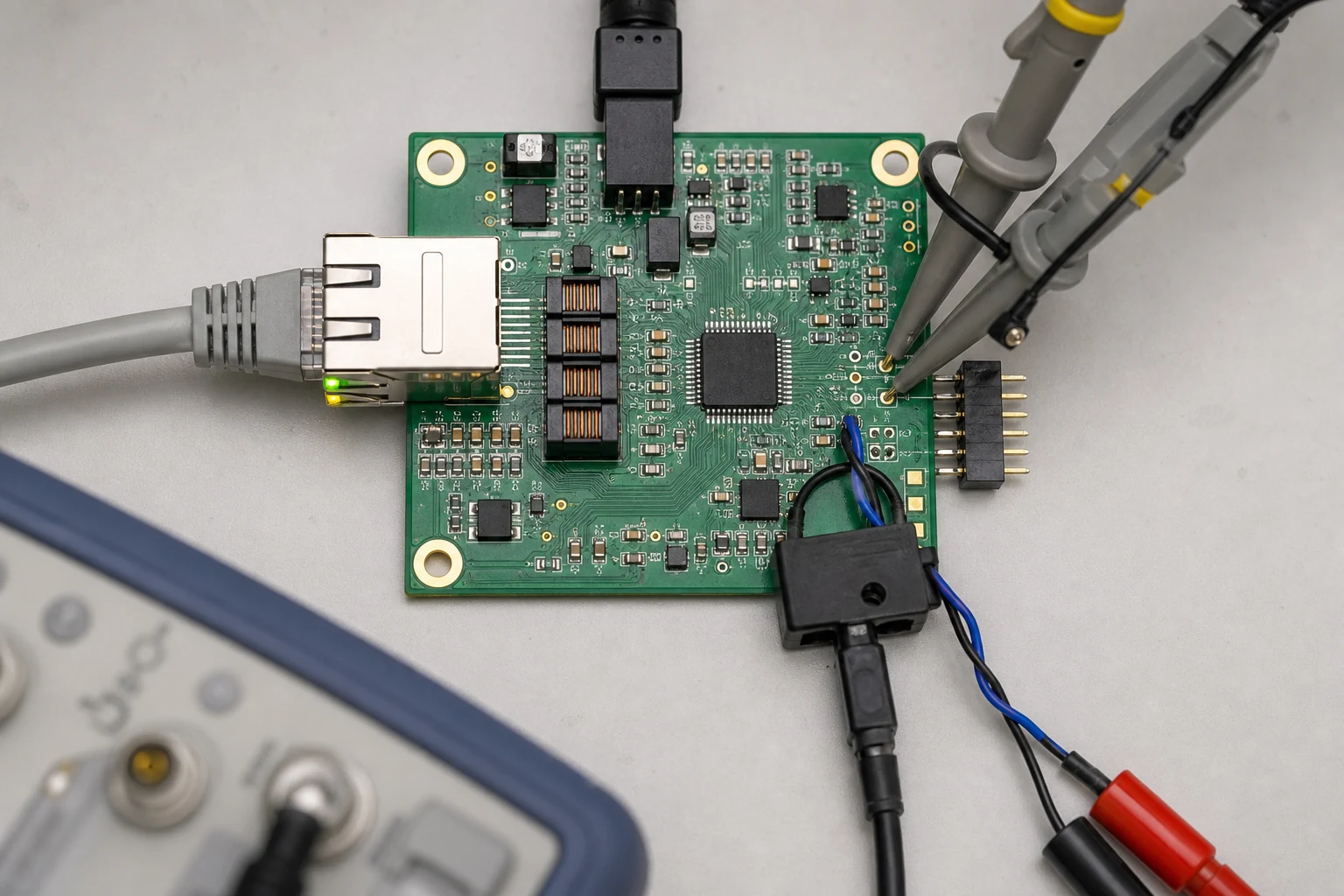
Low-power idle only matters when the PHY state change, analog front end, and measured board current all tell the same story.
What Energy Efficient Ethernet changes on a real board
Energy Efficient Ethernet, defined by IEEE 802.3az, lets an Ethernet link spend part of its idle time in a low-power idle state instead of continuously operating at normal active-idle power. At product level that sounds simple: less traffic should mean less power. At board level it is more conditional. The PHY has to support the feature, the link partner has to negotiate it, firmware or driver settings must not quietly disable it, and the power measurement method has to separate PHY savings from the rest of the board load.
That is why teams often overestimate the benefit during planning and underestimate the validation work later. On a board with a hungry application processor, backlit display, isolated DC/DC stages, and PoE front end, PHY savings may be real but easy to bury inside the total system current. On a compact Ethernet node with one external PHY and long idle periods, the reduction can be easier to justify.
Low-power idle is a signaling behavior, not just a checkbox
The most useful way to think about Energy Efficient Ethernet is as a controlled traffic pause with defined refresh behavior. During low-power idle, the transmitter does not behave like a dead port. It periodically sends refresh signals so link integrity is preserved and the receiver can wake in time when data returns. If that timing or negotiation path is misread, engineers can confuse an expected low-power transition with a marginal link, intermittent wake issue, or cable problem.
That distinction affects design review. If the schematic simply labels the PHY as “EEE capable” but nobody checks default strap options, MDIO register handling, driver policy, or switch compatibility, the board may ship with the feature effectively disabled or with wake behavior that only appears acceptable in one lab setup. This is where firmware and hardware ownership need to meet early rather than after EMC or field complaints.
Where board-level implementation usually goes wrong
Most EEE failures are not caused by the standard itself. They come from ordinary Ethernet design weaknesses that become more visible once the link changes power state. Three patterns show up often.
PHY configuration and negotiation assumptions
Some PHYs support EEE only on certain speeds, revisions, or firmware settings. Others expose separate controls for advertisement, wake timing, or power modes. If software assumes the feature is enabled by default while the strap pins or boot code say otherwise, the validation team can spend hours looking for power savings that never had a chance to appear.
Marginal analog paths around the magnetics
Low-power idle does not excuse weak layout. Poor connector escape, noisy return paths, mismatched pair breakout, or careless center-tap handling can still create link instability that looks like an EEE problem. A board that is already near its signal-integrity limit may pass a casual ping test yet behave badly when link state transitions become frequent. The same layout discipline described in the RJ45 pinout guide still matters here.
Measurement setups that hide the result
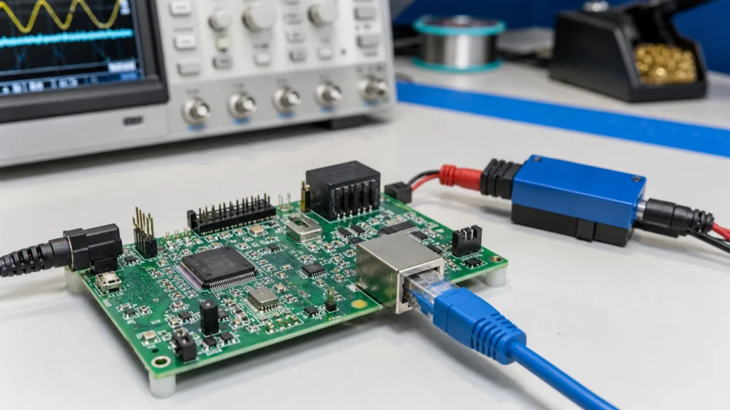
Teams often place the ammeter too far upstream. If the measurement includes DC/DC inefficiency, PoE extraction losses, LEDs, processor load swings, or sensor activity, the PHY savings can disappear inside system noise. For EEE validation, it is better to measure at least one rail that isolates PHY-domain behavior or to correlate MDIO state, traffic state, and current capture together.
How to review an Energy Efficient Ethernet design before layout release
A worthwhile review starts with four questions.
- Does the selected PHY support IEEE 802.3az at the intended speed and interface mode? Some devices support the feature only on specific ports or configurations.
- Will the link partner also negotiate EEE in the target product environment? A lab switch may behave differently from the installed switch, router, backplane, or industrial controller.
- Can the board expose enough observability? MDIO access, current test points, and firmware logging shorten debug cycles dramatically.
- Are surge and connector-side protections already disciplined? If common-mode behavior is messy near the jack, EEE troubleshooting becomes harder because link-state problems and protection-path problems can overlap.
This is also a DFM and DFT issue. If the board leaves no clean current-sense access to the PHY domain and no straightforward way to read negotiated EEE status during manufacturing test, later claims about “power-saving Ethernet” are hard to verify. Even a small test pad strategy can save repeated bench rework.
When EEE helps and when it becomes noise in the power budget
EEE is most useful when the Ethernet link sits idle for meaningful stretches and the PHY power is large enough relative to the total node power to matter. A sensor gateway, building automation controller, low-duty remote terminal, or lightly loaded embedded Linux board can fit that pattern. In those cases, the feature may be worth both the design attention and the product-marketing line item.
It is less impressive when the Ethernet block is a small slice of system power or when traffic patterns are almost continuously active. A video endpoint, industrial controller with deterministic cyclic traffic, or board whose thermal problem is driven by processors and converters may gain little. In those cases, EEE can still work correctly, but it should not distract from bigger power drivers such as regulator efficiency, DDR activity, or PoE conversion losses.
What PHY documentation actually confirms
Vendor documentation supports the mechanism, not a universal whole-product power claim. For example, the Microchip VSC8572 datasheet describes IEEE 802.3az operation as transitions between active and low-power idle with refresh activity, and notes that energy use follows bandwidth utilization. Texas Instruments also describes the quiet and refresh behavior that lets an EEE-capable PHY preserve link operation while reducing idle activity in its EEE application note.
That is why validation should record both the relevant PHY rail and the complete product input. A measured PHY-domain reduction can be genuine while the product-level change remains small because other rails dominate the load. Treat those as two separate measurements in the design review.
Special caution when PoE or industrial links are involved
EEE and PoE are not mutually exclusive, but they create a more crowded review space. Once the same connector region also carries powered-pair entry, surge stress, common-mode termination, and shield/chassis decisions, the debug picture gets noisier. A designer can mistakenly blame EEE for a wake or link issue that is really caused by return-current routing, an overstressed TVS path, or thermal behavior in the powered front end. That is one reason it helps to keep connector protection decisions explicit; ReversePCB’s TVS suppressor diode guide covers the protection side in more detail.
Industrial links deserve another caveat: some systems care more about predictable wake and support simplicity than about modest idle-power savings. If the field environment includes old switches, long service intervals, and low tolerance for intermittent complaints, the engineering answer may be to qualify EEE carefully or disable it deliberately. That is not a failure. It is a system tradeoff.
Validation checks that catch problems before field release
The best validation plan ties protocol behavior to physical evidence.
- Confirm negotiation state. Read the PHY registers or driver status instead of assuming the feature is active because the datasheet says it exists.
- Capture idle and wake transitions. Correlate traffic start, wake time, and current change on the relevant rail.
- Run multiple link partners. A managed switch in the lab is not enough if the product will also connect to low-cost switches, industrial endpoints, or PoE infrastructure.
- Inspect connector-side layout after assembly. Cold solder on shield tabs, imperfect jack seating, or stressed magnetics pins can create symptoms that mimic protocol instability.
- Document the expected savings honestly. Record both PHY-domain reduction and whole-product reduction so later teams do not repeat unrealistic assumptions.
For repair work, remember that “EEE instability” can be a misleading label. A damaged magnetics module, marginal reference clock, poor grounding at the connector shell, or partially failed surge network can all show up first during low-traffic wake behavior because that is when the margin is easiest to disturb.
Use Energy Efficient Ethernet as a design decision, not a marketing default
Energy efficient ethernet is valuable when the link, PHY settings, power budget, and validation method all support it. It is much less valuable when the board cannot prove the savings, the field network is inconsistent, or the product has bigger power problems elsewhere. The engineering win is not enabling IEEE 802.3az on paper. It is knowing whether low-power idle improves the real product enough to justify the additional qualification and support burden.
FAQ
What is Energy Efficient Ethernet in IEEE 802.3az?
Energy Efficient Ethernet is an Ethernet power-saving feature that allows a negotiated link to enter low-power idle when no data needs to be sent, while still preserving link integrity with refresh signaling.
Does Energy Efficient Ethernet reduce total product power by a large amount?
Not always. The savings may be meaningful at the PHY rail but modest at whole-product level if processors, converters, displays, or PoE circuitry dominate the power budget.
Why does EEE sometimes create debugging complaints during bring-up?
Because engineers may mistake low-power idle and wake behavior for a bad cable, unstable link, or firmware issue. Marginal layout, incorrect PHY configuration, and weak measurement setup can all hide the real cause.
Should PoE devices use Energy Efficient Ethernet?
They can, but PoE designs need extra review around surge protection, center taps, current paths, and real system-level power benefit. In some products the support complexity outweighs the idle-power gain.