What is DMA2D?
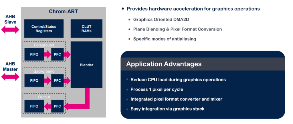
With the advancement of embedded graphics, microcontrollers are taking on increasingly complex graphic computation and display tasks. However, the CPU’s processing power may not suffice for handling high-resolution and vibrant-color graphics. Fortunately, starting from the STM32F429, an external peripheral akin to a GPU has been introduced into STM32 microcontrollers by ST, known as the Chrom-ART Accelerator or DMA2D. DMA2D provides acceleration in many 2D graphical scenarios and effectively integrates functions similar to a “GPU” found in modern graphics cards.
Though DMA2D only offers 2D acceleration and its capabilities are relatively basic compared to GPUs in PCs, it can fulfill most graphics display acceleration requirements in embedded development. By leveraging DMA2D effectively, we can achieve smooth and stunning UI effects on microcontrollers.
DMA2D Functions
- Color Filling (Rectangular Areas)
- Image (Memory) Copying
- Color Format Conversion (e.g., YCbCr to RGB or RGB888 to RGB565)
- Transparency Blending (Alpha Blend)
The first two are memory-based operations, while the latter two involve computational acceleration. Transparency blending and color format conversion can be combined with image copying, providing significant flexibility.
In practical development, the usage of DMA2D bears similarity to traditional DMA controllers. In certain non-graphical scenarios, DMA2D can even replace conventional DMA for certain tasks.
It’s important to note that DMA2D accelerators in different ST product lines might have slight differences. For instance, the DMA2D in the STM32F4 series MCU lacks the capability to convert between ARGB and AGBR color formats. Therefore, when needing a specific functionality, it’s advisable to consult the programming manual to confirm its support.
DMA2D Operating Modes
Similar to how traditional DMA has peripheral-to-peripheral, peripheral-to-memory, and memory-to-peripheral modes, DMA2D, as a DMA component, also comes in four operating modes:
- Register to Memory
- Memory to Memory
- Memory to Memory with Pixel Color Format Conversion
- Memory to Memory with Pixel Color Format Conversion and Transparency Blending
The first two modes involve straightforward memory operations, while the latter two modes perform memory copying while concurrently handling color format conversion and/or transparency blending as required.
DMA2D and HAL Library
In many cases, using the HAL library simplifies code writing and enhances portability. However, there’s an exception when it comes to using DMA2D. The main issue with HAL lies in its excessive nesting and safety checks, which reduce efficiency. While the efficiency loss when dealing with other peripherals might not be substantial, for DMA2D – an accelerator focused on computation and speed – using the HAL library can significantly diminish its acceleration efficiency.
Consequently, we often avoid using relevant HAL functions for DMA2D operations. For efficiency’s sake, direct register manipulation is employed, ensuring maximum acceleration benefits.
Since the majority of DMA2D use cases involve frequent changes in operating modes, the graphical configuration of DMA2D in CubeMX loses its practicality.
Application of DMA2D in Embedded Graphics Development
Tools Required
- STM32 Development Board with DMA2D Peripheral x1
- Color TFT Display Screen x1
In this example, we use the ART-Pi development board by RT-Thread, featuring an STM32H750XB with a clock frequency of up to 480MHz and 32MB of SDRAM. It also includes a debugger (ST-Link V2.1). And we use a 3.5″ TFT LCD display screen with an RGB666 interface and a resolution of 320×240 (QVGA).

Development Environment
The content and code presented in this article can be used in various development environments like RT-Thread Studio, MDK, IAR, etc.
Before starting the experiments in this article, you need a basic project that drives the LCD display using framebuffer technology. Enabling DMA2D is required before running any of the code provided.
DMA2D can be enabled using this macro:
__HAL_RCC_DMA2D_CLK_ENABLE();
Application Project: Rectangle Filling
Embedded graphics encompass various types of operations, including rectangle filling, memory copying, transparency blending, etc. We’ll use rectangle filling as an example. The goal is to create a simple bar chart using DMA2D for rectangle filling:

Firstly, we need to fill the screen with a white color, serving as the background for the pattern. This step is crucial, as the existing pattern on the screen might interfere with our intended design. Then, the bar chart is constructed using four blue rectangular blocks and a line segment, which can be considered a special rectangular block with a height of 1. Hence, drawing this graphic involves a series of “rectangle filling” operations:
- Fill a rectangle with white color, covering the entire screen.
- Fill four data bars with blue color.
- Fill a line segment with black color, with a height of 1.
Essentially, drawing a rectangle of any size at any position on the canvas involves setting the pixel data at the corresponding memory location to the desired color. However, due to the linear storage of the framebuffer in memory, unless the rectangle’s width exactly aligns with the screen’s width, the seemingly continuous rectangular areas have non-contiguous memory addresses.
The diagram below depicts a typical memory layout, where numbers indicate the memory address of each pixel in the frame buffer (offset relative to the base address, without considering multi-byte pixels). The blue area represents the rectangle to be filled. It’s evident that the memory addresses within the rectangle are not contiguous.

This property of the framebuffer prevents us from using efficient operations like memset to fill rectangular regions. Typically, we’d use a nested loop approach like the one below to fill any rectangle. Here, xs and ys are the coordinates of the top-left corner of the rectangle on the screen, width and height define the dimensions of the rectangle, and color specifies the fill color:
					for (int y = ys; y < ys + height; y++) {
    for (int x = xs; x < xs + width; x++) {
        framebuffer[y][x] = color;
    }
}
While the code may seem simple, during execution, a substantial number of CPU cycles are wasted on operations such as condition checks, address computations, and increments, with a minimal portion dedicated to actual memory writing. This situation leads to decreased efficiency.
In such cases, the DMA2D’s register-to-memory working mode comes into play. DMA2D can swiftly fill a rectangular memory region, even if the area is non-contiguous in memory.
Using the example depicted in the image above, let’s delve into how this is achieved:

Firstly, since we’re dealing solely with memory filling and not copying, we need DMA2D to operate in register-to-memory mode. This is achieved by setting bits [17:16] of the DMA2D’s CR register to ’11’, as shown in the code snippet:
DMA2D->CR = 0x00030000UL;
Next, we inform DMA2D about the attributes of the rectangle to be filled, such as the starting address of the region, its width in pixels, and its height.
The starting address of the region is the memory address of the top-left pixel of the rectangle (address of the red pixel in the diagram), managed by the OMAR register of DMA2D. The width and height of the rectangle are both in pixels and are managed by the high 16 bits (width) and low 16 bits (height) of the NLR register. The code for setting these values is as follows:
					DMA2D->OMAR = (uint32_t)(&framebuffer[y][x]); // Set the starting pixel memory address for filling
DMA2D->NLR  = (uint32_t)(width << 16) | (uint16_t)height; // Set the width and height of the rectangle
Subsequently, as the memory addresses of the rectangle are non-contiguous, we need to instruct DMA2D to skip a certain number of pixels after filling one row of data (i.e., the length of the yellow area in the diagram). This value is managed by the OOR register. Calculating the number of pixels to skip has a simple method: subtract the rectangle width from the display area width. The code to implement this is:
DMA2D->OOR = screenWidthPx - width; // Set the row offset, i.e., skip pixels
Finally, we need to inform DMA2D of the color to be used for filling and the color format. These are managed by the OCOLR and OPFCCR registers, respectively. The color format is defined by the LTDC_PIXEL_FORMAT_XXX macros. The code is as follows:
					DMA2D->OCOLR   = color; // Set the color for filling
DMA2D->OPFCCR  = pixelFormat; // Set the color format, e.g., use the macro LTDC_PIXEL_FORMAT_RGB565 for RGB565
With all settings in place, DMA2D has acquired all the necessary information to fill the rectangle. To initiate the transfer, we set bit 0 of the DMA2D’s CR register to ‘1’:
DMA2D->CR |= DMA2D_CR_START; // Start DMA2D data transfer, where DMA2D_CR_START is a macro with the value 0x01
Once the DMA2D transfer begins, we simply wait for its completion. After DMA2D finishes the transfer, it automatically resets bit 0 of the CR register to ‘0’, enabling us to wait for the completion using the following code:
while (DMA2D->CR & DMA2D_CR_START) {} // Wait for DMA2D transfer completion
Tip: If you’re using an operating system, you can enable the DMA2D transfer complete interrupt. Then, you can create a semaphore, wait for it after starting the transfer, and release it in the DMA2D transfer complete interrupt service routine.
For the sake of function generality, the starting transfer address and row offset are calculated outside the function and passed in. Here’s the complete function code:
					static inline void DMA2D_Fill(void * pDst, uint32_t width, uint32_t height, uint32_t lineOff, uint32_t pixelFormat, uint32_t color) {

    /* Configure DMA2D */
    DMA2D->CR      = 0x00030000UL;                                  // Configure for register-to-memory mode
    DMA2D->OCOLR   = color;                                         // Set the color for filling (format should match the configured color format)
    DMA2D->OMAR    = (uint32_t)pDst;                                // Starting memory address of the fill region
    DMA2D->OOR     = lineOff;                                       // Row offset, i.e., skip pixels (in pixel units)
    DMA2D->OPFCCR  = pixelFormat;                                   // Set the color format
    DMA2D->NLR     = (uint32_t)(width << 16) | (uint16_t)height;    // Set the width and height of the fill region (in pixel units)

    /* Start transfer */
    DMA2D->CR   |= DMA2D_CR_START;

    /* Wait for DMA2D transfer completion */
    while (DMA2D->CR & DMA2D_CR_START) {}
}
For convenience, let’s wrap this in a rectangle filling function based on your screen’s coordinate system:
					void FillRect(uint16_t x, uint16_t y, uint16_t w, uint16_t h, uint16_t color) {
    void* pDist = &(((uint16_t*)framebuffer)[y*320 + x]);
    DMA2D_Fill(pDist, w, h, 320 - w, LTDC_PIXEL_FORMAT_RGB565, color);
}
Finally, let’s use the code to draw the chart presented at the beginning of this section:
					// Fill background color
FillRect(0,   0,   320, 240,  0xFFFF);
// Draw data bars
FillRect(80,  80,  20,  120,  0x001F);
FillRect(120, 100, 20,  100,  0x001F);
FillRect(160, 40,  20,  160,  0x001F);
FillRect(200, 60,  20,  140,  0x001F);
// Draw X-axis
FillRect(40,  200, 240, 1,    0x0000);
The code operation effect is as follows:

IC and Semiconductor Design Notes for DMA2D Project in Embedded Graphics
These additions address practical search intent while preserving the original page structure and existing ranking content.
- Review process technology, package, pin pitch, thermal resistance, I/O voltage, ESD rating, and power sequencing before system integration.
- For advanced packaging, verify substrate, bump pitch, redistribution layer, underfill, and assembly yield limits with the manufacturer.
- Plan testability with boundary scan, accessible power rails, boot strapping visibility, and measurable clock or reset nodes.